Cesky: |
DispHSTX
DVI (HDMI) and VGA display driver for Pico2 RP2350, using HSTX peripheral
Version 1.01, March 2025
(c) Miroslav Nemecek
https://github.com/Panda381/DispHSTX

Basic
description
License
Schematic wiring
diagram
Files and building
Divided screen
Test
Links
History of versions
DispHSTX is a driver for Pico2 RP2350 microcontroller, both in ARMv8 and RISC-V Hazard3 mode, allowing to generate DVI (HDMI) and VGA video signal, using HSTX peripheral. It supports 40 different image formats - 9 modes of pixel graphics, 2 text modes, attribute compression, RLE and HSTX compression. Functions for drawing geometric shapes, images and texts are provided for 8 basic graphic modes. The drawing library supports a back buffer - it updates the boundaries indicating the modified "dirty area". If memory is insufficient, the back buffer can be used in strip mode. Several different image formats can be combined on one screen simultaneously by dividing the screen into strips and slots. In both modes, DVI (HDMI) and VGA, color resolution up to 16 bits per pixel is possible. Although in VGA mode the output is only via a 6-bit RGB converter, higher colour resolution is achieved by the Pulse Pattern Modulation PPM, the display is visually close to the 15-bit display. The timing of the generated video signal is limited only by the overclocking capabilities of the microcontroller used. It is usually possible to achieve a resolution of up to 1440x600 pixels.
DispHSTX is built on the PicoLibSDK library, but interface to original Raspberry PicoSDK library is ready too.
DispHSTX driver source code is completely free to use for any purpose, including commercial use. It is possible to use and modify all or parts of the driver source code without restriction.
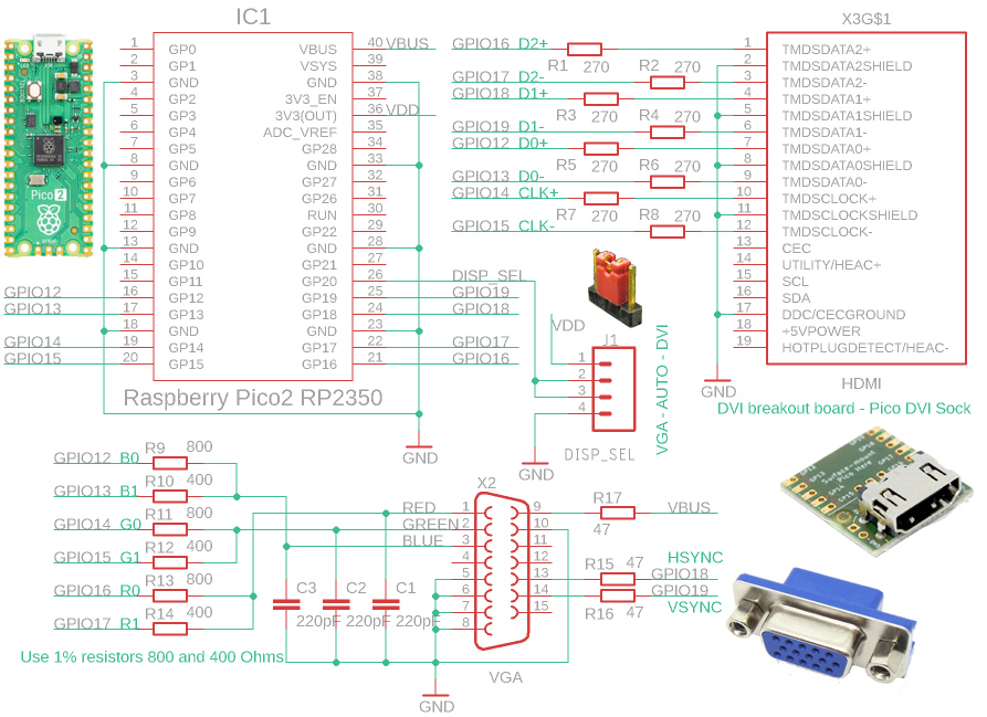
The DVI (HDMI) and VGA connectors are connected to the same processor pins, GPIO 12 to GPIO 19. The selection of pins 12 to 19 is determined by the processor and cannot be changed. In the driver configuration there are 3 options for the pin order for the DVI (HDMI) output, but any other pin order can be selected after editing the code. It is recommended to use the default configuration 0 (see diagram), which is based on the wiring of the popular Pico DVI socket. Similarly, it is possible to select any pin order for the VGA connector, but it is recommended to keep the order used in the schematic above to allow VGA signal output from the PIO controller, which requires keeping the pin order.
The 400 and 800 ohm resistors used for the VGA output should be used within a 1% tolerance. If necessary, close values such as 390 and 820 ohms can be used, but the smoothness of the gradient transition may be degraded for multi-color modes (12 to 16 bits per pixel).
On the RGB outputs of the VGA connector 220pF capacitors are used to filter Pulse Pattern Modulation PPM. For video modes with a low system frequency, it may be beneficial to increase the value of the capacitors to reduce potential image grain. For video modes with high system frequency, it may be beneficial to increase the value of the capacitors to increase the sharpness of the image.
Any GPIO pin can be used for the switch to select VGA/DVI mode, or the switch does not need to be used. If the switch is not used or it is in the middle position, an automatic detection of the VGA monitor connection can be used to select the mode.
The DispHSTX driver is primarily prepared for use with the PicoLibSDK library. The main driver files can be found in the _display/disphstx folder. The disphstx_dvi.* files provide support for the DVI (HDMI) output. The disphstx_vga.* files are used to handle the VGA output. The disphstx_vmode_time.* files contain video mode timing definitions - you can use them to define your own video mode. The disphstx_vmode_format.* files contain definitions of graphic formats. Rendering of graphic formats is done in the *_render.* files in the C codes - these functions are used only as a reference to the correct code functions. The actual rendering is done using functions optimized by the assembler, in the *.S files.
The _config.h file contains the default definitions of the driver parameter settings. If you need to change a configuration switch, specify it in the config.h file in the project folder. Default switches are used if they are not found in the project's config.h file. The main switch you will need to include in config.h is "#define USE_DISPHSTX 1". This will ensure that the DispHSTX driver functions are compiled and made available. The second important switch you may need to include is "#define USE_DRAWCAN 1". This will provide access to the DrawCan drawing library functions. For more info about projekt configuration switches, see chapter "Configuration".
The HSTX driver is by default run in the second core of the processor. This is required by the fact that the driver operation must not be disturbed by anything to avoid dropping the generated signal. For this reason, no interrupts other than those from the HSTX driver may be running in the second core of the processor. All time-consuming operations must be performed from RAM, not from Flash - the linker must provide a "time_critical" section in RAM for this purpose.
Driver functionality is provided for both ARMv8 processor mode and RISC-V Hazard3 mode. However, it is necessary to take into account that the code for RISC-V mode is slightly slower (about 15%) and so the HSTX driver in RISC-V mode may load the processor a bit more than in ARM mode.
The driver in the basic full setup can take quite a lot of RAM for functions and auxiliary buffers (about 50 KB). You can reduce the memory requirements by limiting functionality - disabling VGA mode, reducing the maximum resolution, or disabling unused image formats. See the "Configuration" chapter for details.
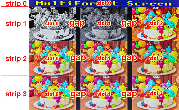
The DispHSTX driver allows you to divide the screen into multiple parts. Vertically, the image can be divided into strips. Each strip can be divided into slots in the horizontal direction. Each slot can contain a different image format.
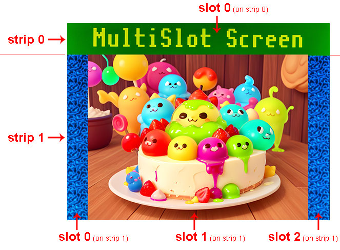
In certain cases, for example, if the format of the generated slot data differs, it may be necessary to insert a separation gap between the slots to provide the necessary time to redefine the controller registers.
Sample graphics with DrawCan library:
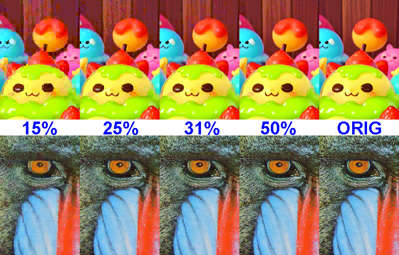
Comparison of attribute compression ratios (display scale 100%):
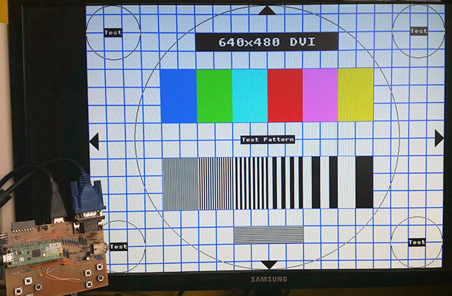
Here are several test programs that will display a test pattern on the DVI or VGA output via the RP2350 HSTX interface. The default pin wiring for DVI Sock or for VGA is used, according to the diagram above. The DVI or VGA output is selected by program selection - no configuration switch or other hardware is required. Video modes 640x480, 800x600, 1024x768, 1280x720 and 1440x600 are ready. Program source files are available in the PicoLibSDK library, Pico2 device.
Download DispHSTX library (source codes and samples)
Download manual for DispHSTX library (formats DOC, ODT, PDF)
DispHSTX on Github: https://github.com/Panda381/DispHSTX
DispHSTX demo sample in PicoLibSDK: https://github.com/Panda381/PicoLibSDK/tree/main/Pico/DispHSTX/HSTXDemo
02/24/2025 Version 1.00.
03/02/2025 Version 1.01, Raspberry PicoSDK library build
Miroslav Nemecek