Cesky: |
CH32LibSDK
SDK library for low-end CH32 RISC-V microcontrollers
Pre-alpha version 0.41, in progress - under development (development suspended)
(c) 2025-2026 Miroslav Nemecek
https://github.com/Panda381/CH32LibSDK
Download library along with sample applications and all resources

Current status of CH32LibSDK library development: Further development of the library has been suspended at this time. Support for the CH32V003 and CH32V00x series processors is fully functional and verified in practice. The CH32X03x series processors should also be fully supported, but they have been tested less and USB support is not available for them. For the CH32L103, CH32V103, CH32V2xx, and CH32V3xx series processors, only part of the SDK functions are ready, some functions are missing, and those processors are not yet supported.
All schematics and printed circuit boards are in Eagle 9.2.0 Free format.
Note on the lifespan of used OLED displays. It is commonly believed that these small OLED displays have a short lifespan. The reason for this is the excessive contrast that developers usually set. Contrast settings of 70 to 90% are often seen in configurations. Overexposure greatly reduces the lifespan of LEDs. I use a contrast of 5 to 10% - the brightness drops only slightly, the current drops to 30 to 50%, and the lifespan of the OLED is significantly increased.
BeatleCalc with emulation of Sinclair Scientific and Datamath calculators
BabyPC - WCH80, ZX80 clone
CH32LibSDK is an SDK library designed to simplify the development of applications with CH32 RISC-V processors. It is focused on low-end processors, typically CH32V003, CH32V002-CH32V007, CH32X033-CH32X035, CH32V103, CH32L103, CH32V203, and CH32V208. Higher-end processors (with Ethernet functionality) are not supported.
The library is currently under development. Many features are missing or have not been tested.
How to compile on Windows, using command line:
- Use FAR Manager to edit
source files and run BAT scripts.
- Download MounRiver Studio v1.92 http://mounriver.com/download
- Install MounRiver Studio.
- Extract "toolchain\RISC-V Embedded GCC12" compiler to
separate folder.
- Edit _c1.bat file and enter path to "bin" folder of
the compiler: set GCC_CH32_PATH=C:\GCC_CH32\bin
- Extract "toolchain\OpenOCD\bin" tool or use openocd
from _tools\openocd.
- Sometimes you may need to use WCH-LinkUtility from the
ExTool\SQWTool folder. It may sometimes be necessary to erase the
flash memory using power-off, because OpenOcd cannot do this.
- Compile sample using c.bat.
- Flash compiled sample using e.bat, with WCH-LinkE programmer
(available here, for example: https://pajenicko.cz/usb-programator-a-debug-adapter-wch-link ). For the SD card version of the console, simply
upload the program to the SD card and load it into the processor
using the boot loader.
- Clear compilation using d.bat.
Game consoles and devices created within the CH32LibSDK library and their properties:
BeatleCalc |
BabyPC - WCH80 |
||||||||
| Processor | CH32V002A4M6 | CH32V002J4M6, CH32V003J4M6, CH32V006F8P6 |
2x CH32V002A4M6 |
CH32V002A4M6 | CH32V002A4M6 | 2xCH32V002A4M6 | CH32V006F8P6 | CH32V006E8R6 | CH32X035G8R6 |
| Socket | SOP16 | SOP8, TSSOP20 | SOP16 | SOP16 | SOP16 | SOP16 | TSSOP20 | QSOP24 | QSOP28 |
| Flash | 16KB | 16KB, 62KB | 2x16KB | 16KB | 16KB | 2x16KB | 62KB | 62KB | 62KB |
| RAM | 4KB | 2KB, 4KB, 8KB | 4KB | 4KB | 4KB | 4KB | 8KB | 8KB | 20KB |
| Clock | 24MHz | 24MHz | 24MHz | 24MHz | 50MHz | 50MHz | 48MHz | 50MHz | 48MHz |
| Crystal | - | - | - | - | 25MHz | 25MHz | - | 25MHz | - |
| Power | CR2032 | CR2032, USB 5V | USB 5V or 3.3V | CR2032 | USB 5V | USB 5V | 1xAAA, step-up 3.3V | USB 3.3V | 1xAA, step-up 3.3V |
| Display | OLED I2C 128x64 SSD1306 B&W, blue-yellow |
OLED I2C 128x64 SSD1306 B&W, VGA mono |
9-digit LED: 2xBQ-M324RD BS-A344RD |
OLED I2C 128x64 SSD1306 B&W |
VGA mono | VGA mono | OLED I2C 128x64 SSD1306 B&W |
VGA 9 colors | LCD SPI 160x80 ST7735S RGB |
| SD card | - | - | - | - | - | - | Yes | Yes | Yes |
| Diagram | diagram | diagram OLED diagram VGA diagram CPU2 diagram CPU6 |
diagram | diagram | diagram | diagram | diagram | diagram | diagram |
| BASIC | - | - | - | - | - | BASIC80 (ZX80) | - | - | - |
| Precision | 21 digits mantissa 2 digits exponent |
- | 13 digits mantissa 2 digits exponent |
- | - | 32-bit integer | - | - | - |
| Prototype | 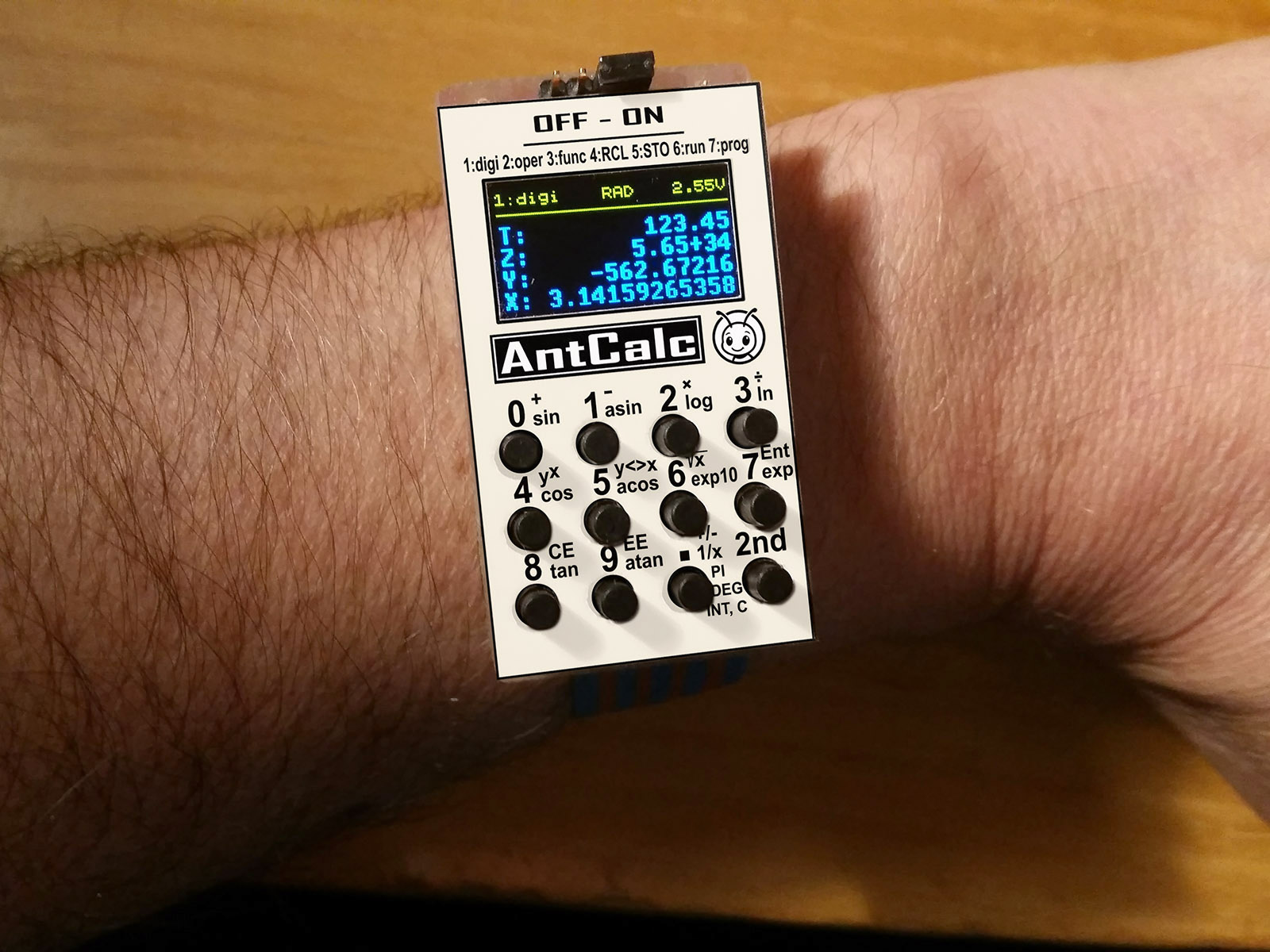 |
|
 |
|
|
|
|
|
|
Sample games created for the CH32LibSDK library game console:
BabyPC - WCH80 |
|||||||
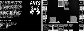
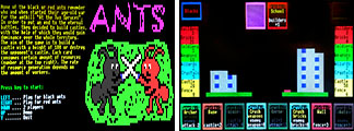
 Ants - a card game. The goal is to build your castle and destroy the opponent's castle. |
--- | --- | mono | mono | --- | color | --- |
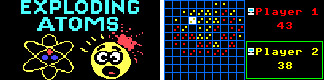
 Atoms - exploding atoms. |
mono | mono | mono | mono | mono | color | color |
 Chess - chess. |
--- | --- | --- | --- | --- | color | --- |
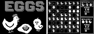
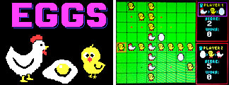 Eggs - transforming stones into eggs-chickens-hens. |
mono | mono | mono | mono | mono | color | color |
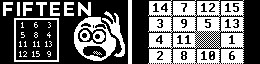
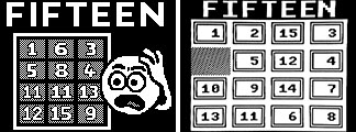
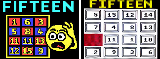
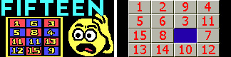
 Fifteen - puzzle, the goal is to arrange the stones back into the correct order. |
mono | mono | mono | mono | mono | color | color |
 Flappy - classic logic puzzle from Sharp MZ800, 105 scenes. |
--- | --- | --- | --- | --- | color | --- |
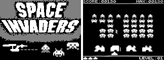
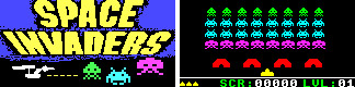
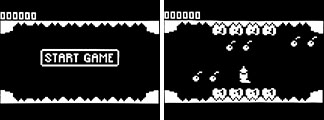
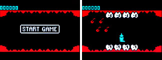
 Invaders - Space Invaders shooting game. |
mono | mono | mono | mono | mono | color | color |
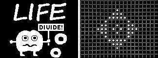
 Life - cell machine. |
mono | mono | mono | mono | mono | color | color |
 Maze - maze puzzle. |
mono | mono | mono | mono | mono | color | color |
 Sokoban - logic puzzle. |
mono | mono | mono | mono | mono | color | color |
 TArkan - Tiny-Arkanoid ((c) Daniel Champagne) |
mono | mono | mono | mono | mono | color | color |
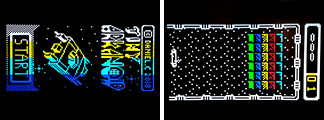
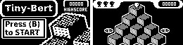
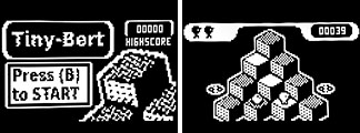
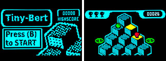
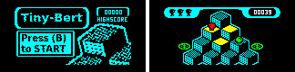 TBert - Tiny-Bert ((c) Daniel Champagne) |
mono | mono | mono | mono | mono | color | color |
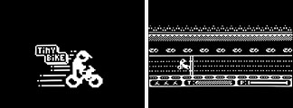
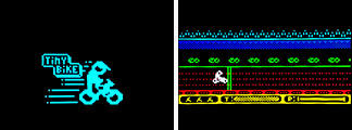
 TBike - Tiny-Bike ((c) Daniel Champagne) |
mono | mono | mono | mono | mono | color | color |
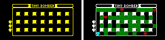 TBomber - Tiny-Bomber ((c) Daniel Champagne) |
mono | mono | mono | mono | mono | color | color |
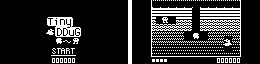
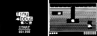
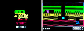
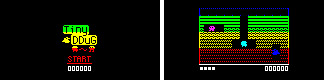
 TDDug - Tiny-DDug ((c) Daniel Champagne) |
mono | mono | mono | mono | mono | color | color |
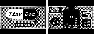
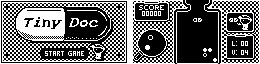
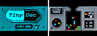
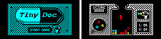
 TDoc - Tiny-Doctor ((c) Daniel Champagne) |
mono | mono | mono | mono | mono | color | color |
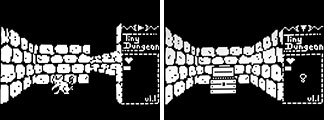
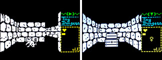
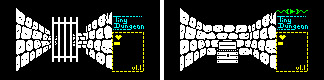 TDungeon - Tiny-Dungeon ((c) Lorandil) |
mono | mono | mono | mono | mono | color | color |
 Tetris |
mono | mono | mono | --- | mono | color | color |
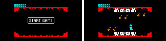
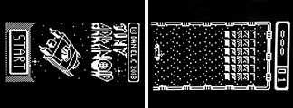
 TInvader - Tiny-Invaders ((c) Daniel Champagne) |
mono | mono | mono | mono | mono | color | color |
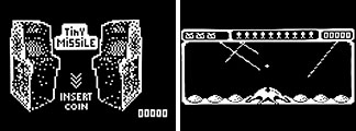
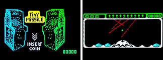
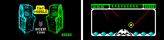
 TMissile - Tiny-Missile ((c) Daniel Champagne) |
mono | mono | mono | mono | mono | color | color |
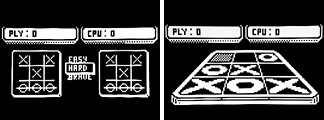
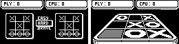
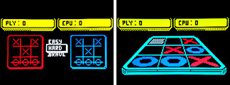
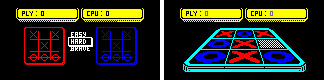
 TMorpion - Tiny-Morpion ((c) Daniel Champagne) |
mono | mono | mono | mono | mono | color | color |
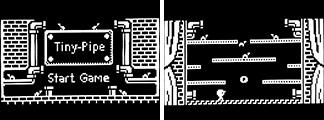
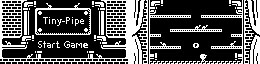
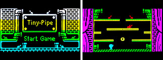
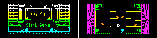
 TPipe - Tiny-Pipe ((c) Daniel Champagne) |
mono | mono | mono | mono | mono | color | color |
 TPlaque - Tiny-Plaque ((c) Daniel Champagne) |
mono | mono | mono | mono | mono | color | color |
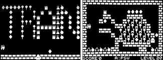
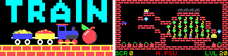
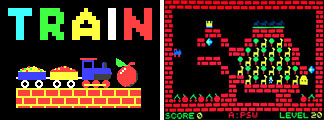 Train - puzzle game. |
mono | mono | mono | mono | mono | color | color |
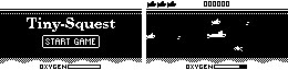
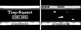
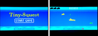
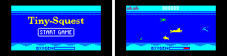 TSQuest - Tiny-SQuest ((c) Daniel Champagne) |
mono | mono | mono | mono | mono | color | color |
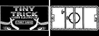
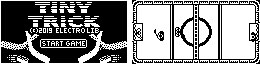
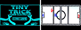
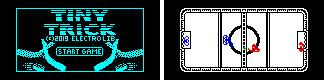 TTrick - Tiny-Trick ((c) Daniel Champagne) |
mono | mono | mono | mono | mono | color | color |
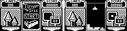
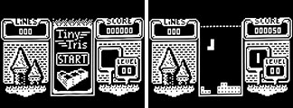
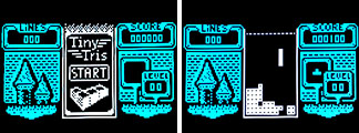
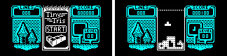
 TTris - Tiny-Tris ((c) Daniel Champagne) |
mono | mono | mono | mono | mono | color | color |
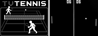
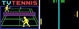
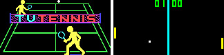
 TVTennis - television tennis. |
mono | mono | mono | mono | mono | color | color |
| Number of games | 25 | 25 | 26 | 25 | 25 | 28 | 25 |
mono = black and white version, color = color version, --- = not implemented
![]()
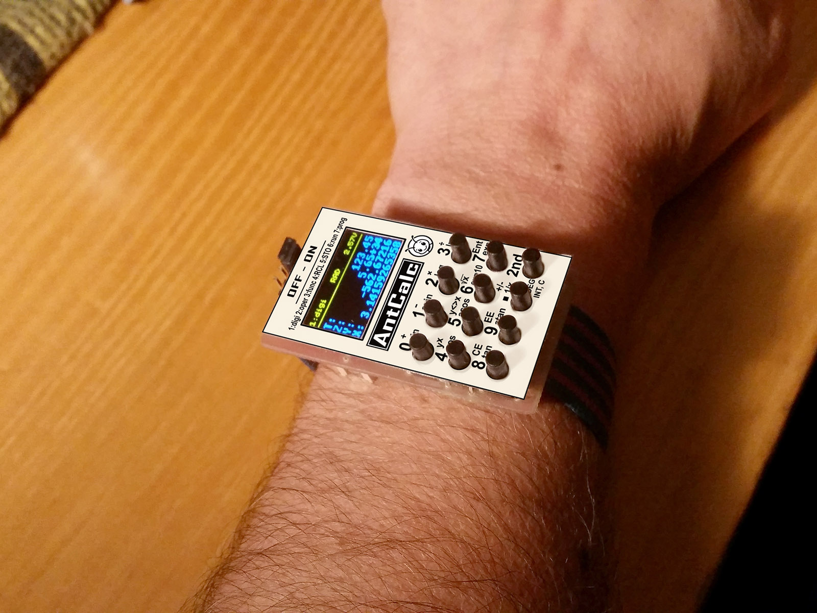
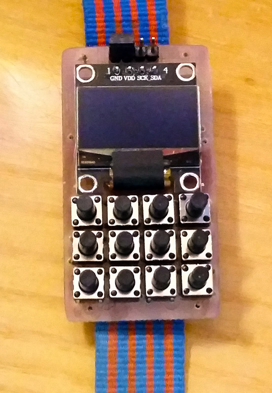
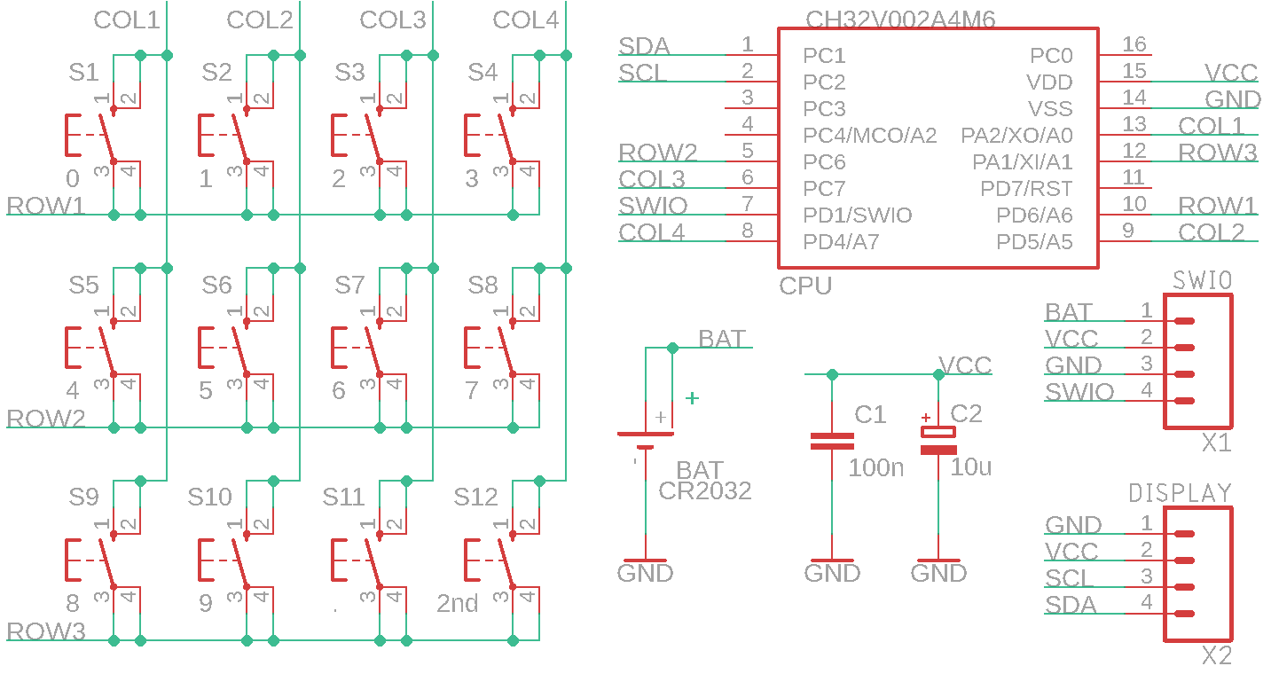
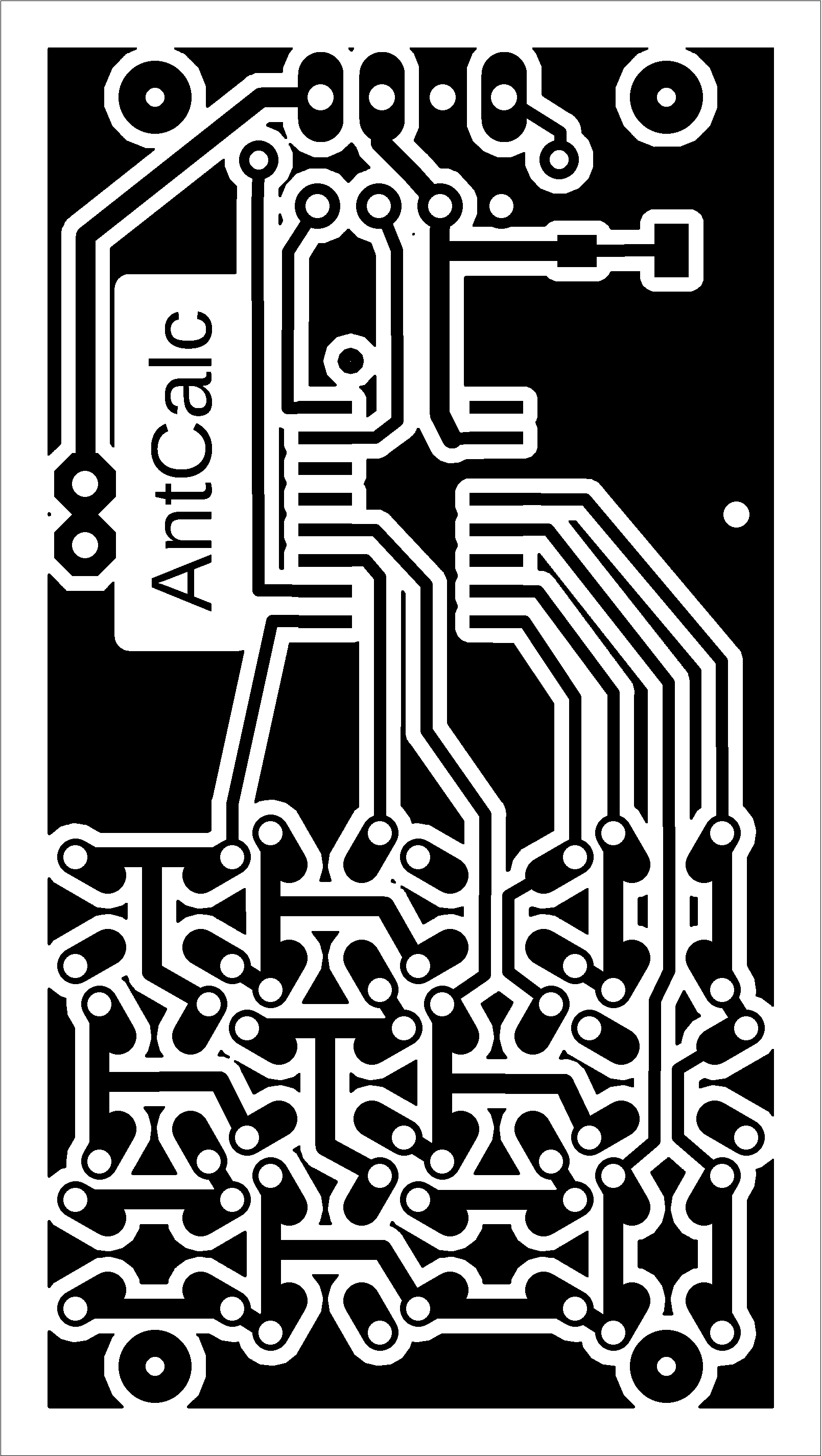
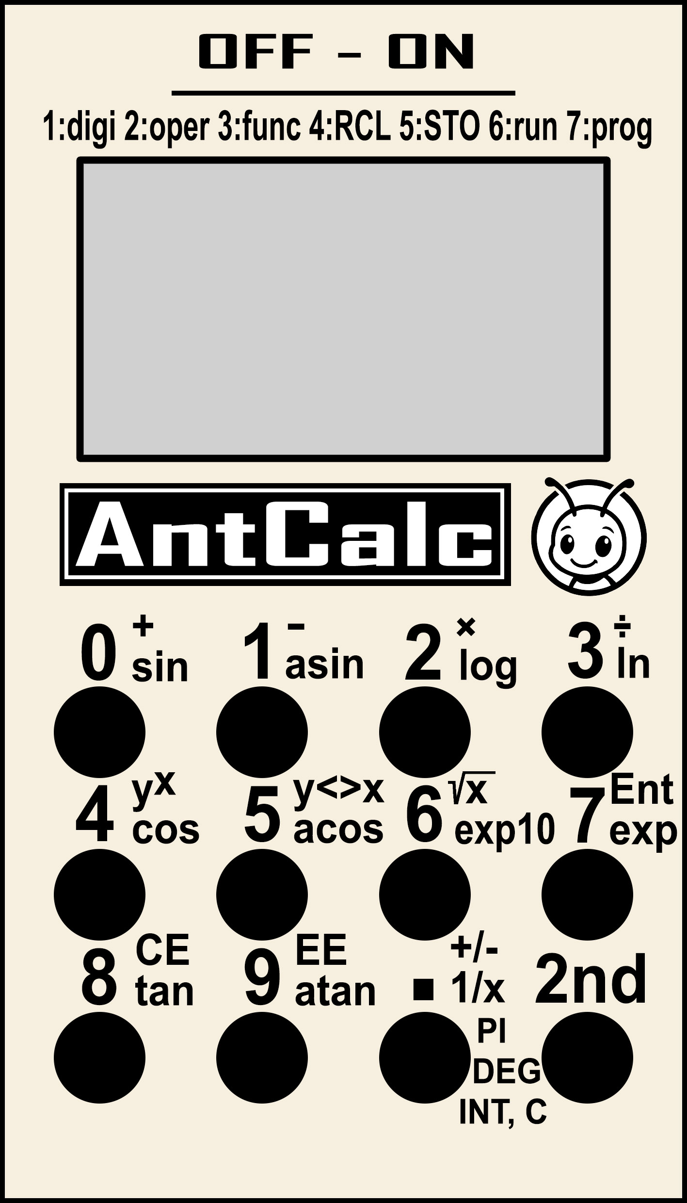
AntCalc is a wrist-worn programmable calculator with scientific functions. It features an inexpensive CH32V002A4M6 processor, a blue-yellow 0.96" I2C OLED display with an SSD1306 controller and a resolution of 128x64 pixels B&W (available here, for example: https://www.hadex.cz/m508c-displej-oled-096-128x64-znaku-iici2c-4piny-modrozluty/). It also has 12 buttons and is powered by a CR2032 battery. The calculator works with reverse Polish notation (RPN), which means that numbers are first entered into the calculator's stack using the Enter button, and then the desired operation is performed by pressing the operator. The calculator's stack has a size of 10 registers. The lowest 4 registers are shown on the display under the names X, Y, Z, and T. The calculator calculates in BCD code with an accuracy of 21 valid digits, along with an exponent in the range of +-99. The display shows a maximum of 14 digits when displayed without an exponent or 11 digits with an exponent. Functions are available for calculating direct and inverse trigonometric functions, power function, decimal and natural logarithmic and exponential functions. The calculator has 10 memory registers, the contents of which are stored in flash memory even when the calculator is turned off. The calculator can be programmed using macros containing a record of keystrokes. Up to 10 macros, each up to 38 keys long, can be loaded into the calculator's memory. The calculator measures 30x55 mm. A jumper is used as a switch on the connector, which is also used to program the processor.
AntCalc calculator functions
The calculator is operated using 12 buttons. 10 buttons are digits, 1 button is a decimal point, and 1 button is 2nd for switching between modes. In total, you can switch between 7 states by repeatedly pressing the 2nd button. If an error occurs during operations (division by zero or square root of a negative number), the text "overflow" is displayed on the X register row. Pressing any key will end the error messages and reset the X register.
0..9 ... enter a digit.
. ... Enter a decimal point. If the calculator is in exponent editing mode, you can use the decimal point button to return to mantissa editing.
2nd ... Switch between additional calculator functions. The selected mode is displayed on the top line of the display on the left.
+, -, *, :, Y^x (2nd 0..4) ... arithmetic operations between registers X and Y
y<>x (2nd 5) ... swap registers X and Y
Vx (2nd 6) ... square root
Enter (2nd 7) ... move number X to register Y
CE (2nd 8) ... Delete the last character during editing. The EE key switches to exponent editing, the dot key switches to mantissa editing. The CE key activates number editing mode if editing is not in progress.
EE (2nd 9) ... Enter exponent. Use the EE key to start editing the number shown on the display. Use the decimal point key to switch to mantissa editing.
+/- (2nd .) ... Change the sign of the mantissa or exponent of the number on the display.
sin (2x2nd 0) ... sine
asin (2x2nd 1) ... arc sine
log (2x2nd 2) ... decimal logarithm
ln (2x2nd 3) ... natural logarithm
cos (2x2nd 4) ... cosine
acos (2x2nd 5) ... arccosine
exp10 (2x2nd 6) ... decimal exponent
exp (2x2nd 7) ... natural exponent
tan (2x2nd 8) ... tangent
atan (2x2nd 9) ... arctangent
1/x (2x2nd .) ... reciprocal value
RCL0..RCL9 (3x2nd 0..9) ... recall memory contents 0 to 9
PI (3x2nd .) ... Pi number
STO0..STO9 (4x2nd 0..9) ... Saving a number to memory 0 to 9. The content is stored in flash memory even when the device is turned off.
DEG (4x2nd .) ... Switching the angular measure of goniometric functions between degrees (DEG) and radians (RAD). The selected setting is displayed in the middle of the top line of the display and is stored in flash memory.
RUN0..RUN9 (5x2nd 0..9) ... Play macro number 0 to 9.
INT (5x2nd .) ... Cut off the decimal part of the number (rounding to whole numbers towards zero).
PRG0..PRG9 (6x2nd 0..9) ... Start recording a macro into program number 0 to 9. The codes of the pressed keys are stored in memory. Up to 38 button codes can be stored in one macro. Presses of the 2nd button are not stored in the program - the resulting function code is stored as 1 code. During macro recording, the text PROG0..PROG9 flashes in the upper right corner of the display, indicating that recording is in progress. If the number of buttons is exceeded, the indicator remains lit but stops flashing to indicate that buttons are no longer being stored. Macro recording can be stopped by pressing any of the PRG0 to PRG9 functions (it is not necessary to use the same macro number).
C (6x2nd .) ... Clears the calculator's registers. The contents of the memory and programs are retained. Turning the calculator off and on has the same effect.
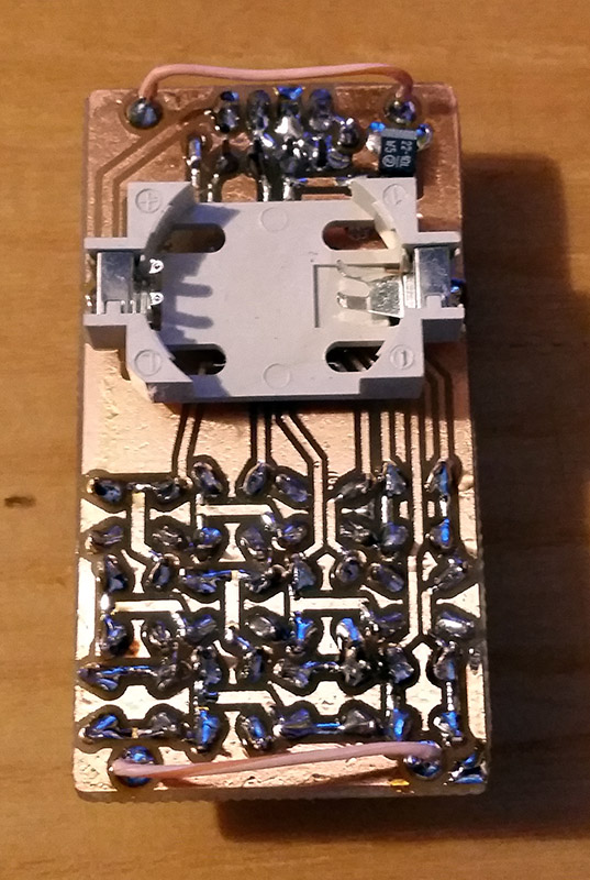
Notes on construction:
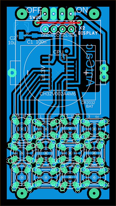
The calculator uses a very inexpensive Chinese processor CH32V002A4M6. It is housed in an SOP16 package with large pin spacing, making the calculator's design suitable even for novice designers. The calculator has two eyelets on the bottom for attaching a strap. To simplify the design, a jumper plugged into the connector, which is also used to program the calculator's processor, was used as a switch. When switched on, the jumper is plugged into the two pins on the right, and when switched off, it is plugged into the two pins on the left. A two-color, blue-yellow OLED display with an SSD1306 controller and a resolution of 128x64 was used. The display is actually monochrome, with the top 16 lines displayed in yellow and the next 48 lines in blue. Alternatively, a monochrome display can also be used. I leave the design of the top cover with button labels to other designers – in the prototype, I only used a paper label with cut-out holes for the buttons.
>>> Source codes and all necessary documentation of the AntCalc calculator can be found in the CH32LibSDK library in the ch32\DEVICE\ folder. https://github.com/Panda381/CH32LibSDK/tree/main/ch32/DEVICE <<<
![]()
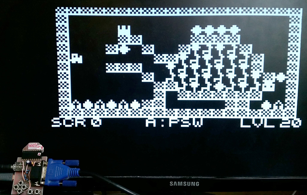
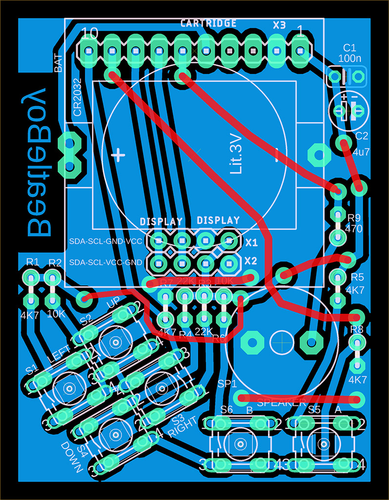
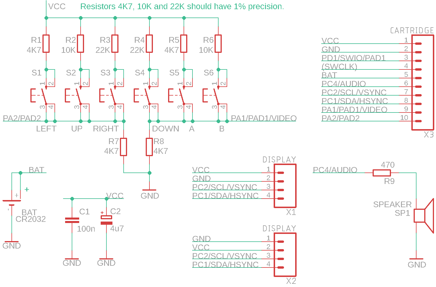
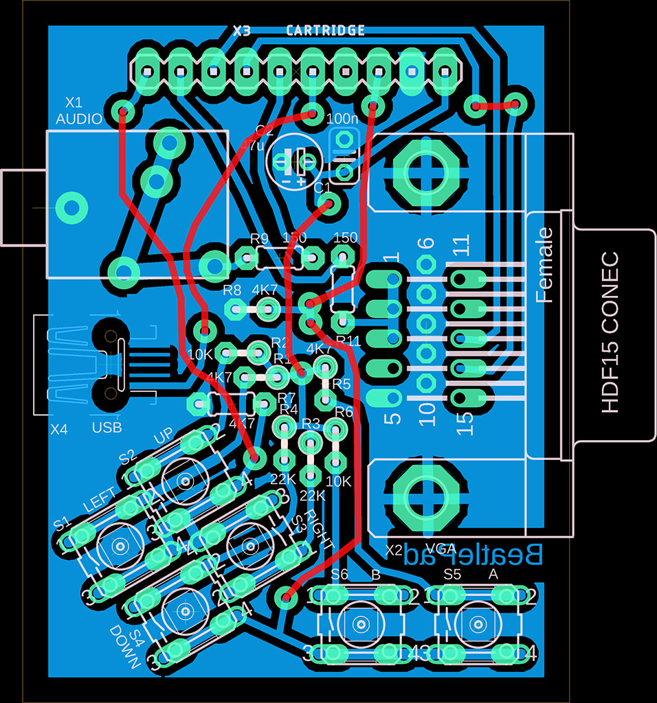
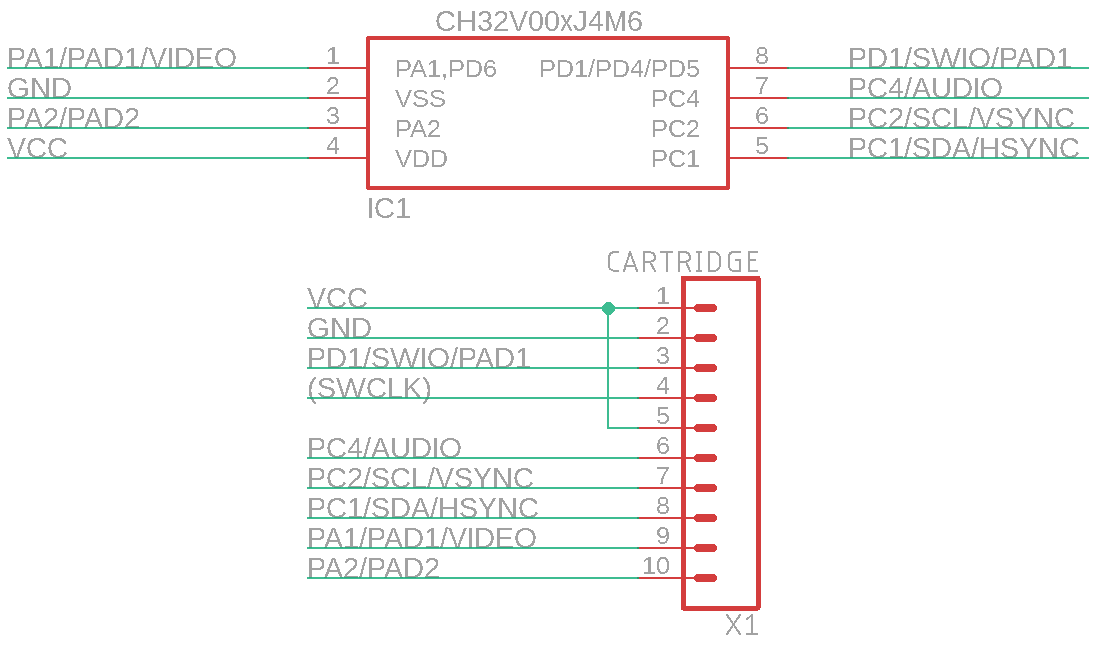
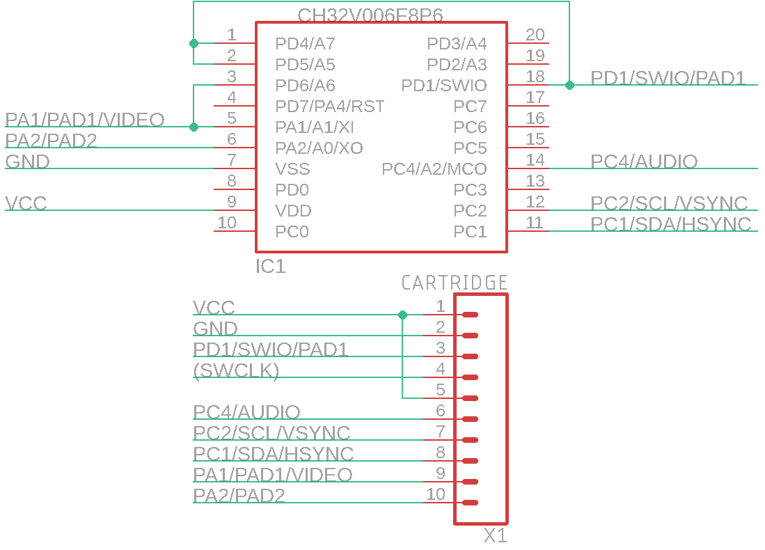
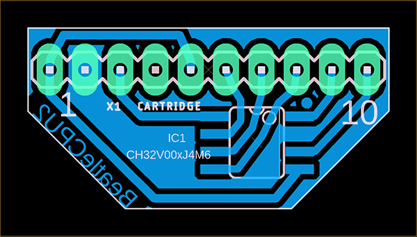
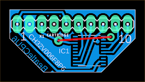
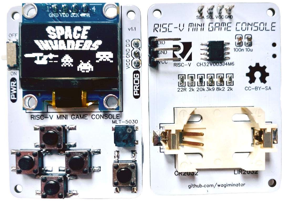
BeatleBoyPad is dual console with interchangeable ROM cartridges. It consists of two consoles. The first console, BeatleBoy, contains 128x64 pixel black and white OLED I2C display with SSD1306 controller, built-in speaker and 6 buttons (4 directional arrows and A and B buttons). The console is powered by CR2032 battery. The second console, BeatlePad, has black and white output to VGA monitor and connector for external speaker. Cartridge with program contains cheap Chinese processor CH32V002J4M6, CH32V003J4M6 or CH32V006F8P6. Note: for processor V006 different cartridge wiring than for processors V002 and V003 is used.
The cartridges are common to both consoles. The processor in the cartridge distinguishes between the two consoles based on the voltage and switches to the appropriate mode accordingly. Due to the console's auto-detection, it is therefore necessary to maintain the power supply used - the BeatleBoy console is powered by a 3V battery, while the BeatlePad console is powered by a 5V external source. In addition to detecting the supply voltage, the processor in the BeatlePad console also detects the connection of a VGA cable. The program in the console will only start after connecting a VGA monitor. This is so that the cartridge can be reprogrammed in the programmer, as the VGA console also uses programming pin.
There are 25 games available for the console. All prepared games can be programmed into all types of cartridges - with V002, V003, or V006 processors. The V002 processor variant has more RAM available than the V003 processor, and the output to the VGA monitor is via SPI controller, which allows the use of higher video mode resolutions (this is not used in the prepared games). The V006 processor has more RAM than the V002 processor. However, unless required by the software, it is recommended to use the CH32V003J4M6 processor. Although this is an older type of processor, its advantage is higher oscillator stability and therefore less noise in the VGA image.
When constructing the device, it is necessary to use resistors with 1% accuracy, otherwise button presses may be detected incorrectly. The brightness of the OLED display is kept low to minimize battery consumption. The current voltage of the CR2032 battery is displayed when most programs start. The measurement is performed using the internal reference of the processor, and therefore the displayed value may vary by up to 10% and should therefore be taken as a guide only. Pay attention to the pin layout of the display - there are usually two versions, with the pin order VCC-GND-SCL-SDA or GND-VDD-SCL-SDA. Both variants are available on the printed circuit board (alternatively, the display can be connected interchangeably via a pin header). The OLED display is used here in an inverted position compared to other consoles - the image rotation is defined in the display initialization sequence.
An internal HSI RC oscillator is used for VGA image output. Its frequency is not stabilized by a crystal, so slight signal timing deviations and image noise must be expected. The V003 processor has slightly lower image noise than the V002 and V006 processors. Some VGA monitors may not display the image due to the low quality of the image signal timing.
Programs can be loaded into the cartridge using the WCH-LinkE programmer (available, for example, here: https://pajenicko.cz/usb-programator-a-debug-adapter-wch-link). Pin number 4 on the cartridge is left as an option for reprogramming processors requiring 2-wire programming (SWDIO+SWCLK, e.g., CH32X035). Currently, this option is not used, and it is possible to use this pin as a blind pin to facilitate cartridge insertion orientation (i.e., cut off pin number 4 on the cartridge and plug the corresponding pin on the console, e.g., with heat shrink tubing).
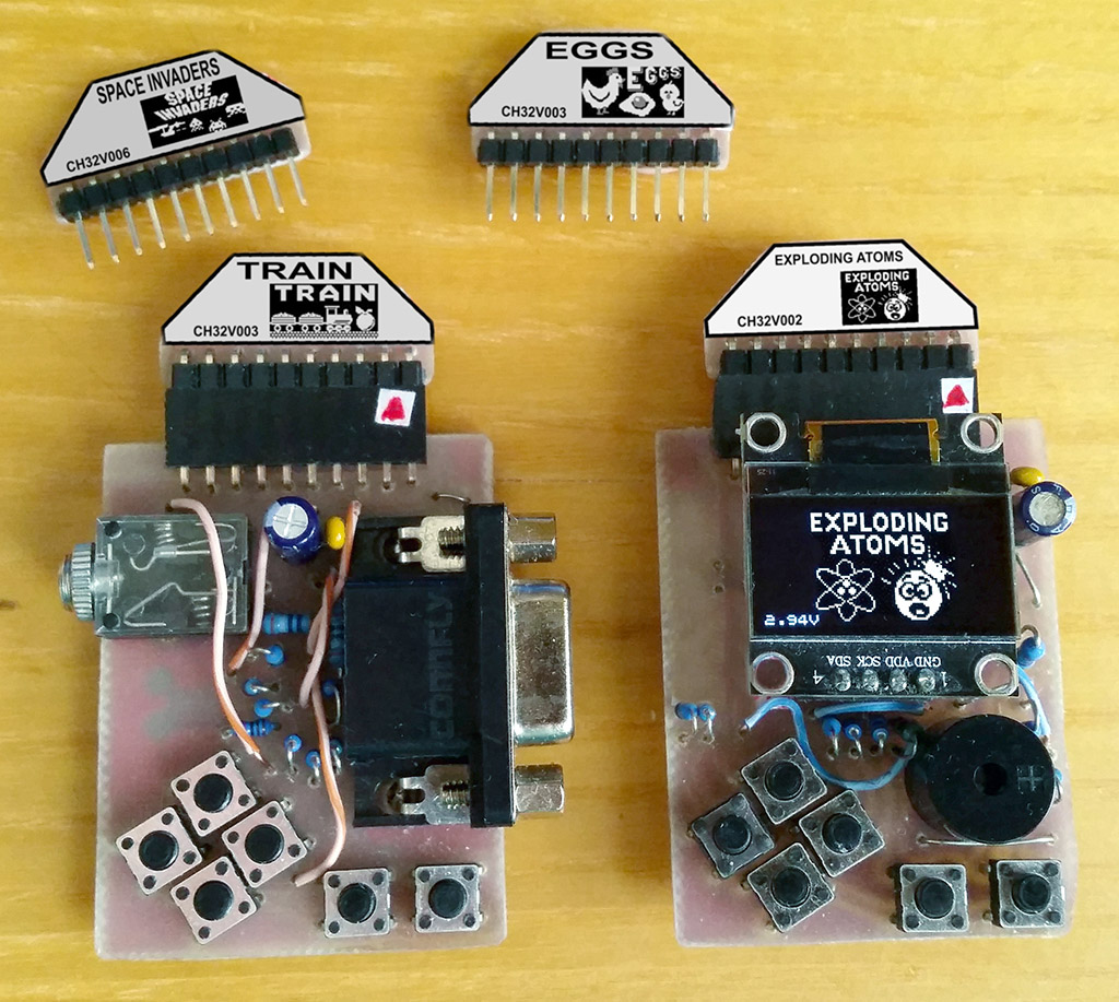
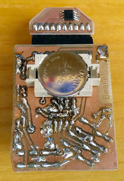
BeatleBoy:
BeatlePad:
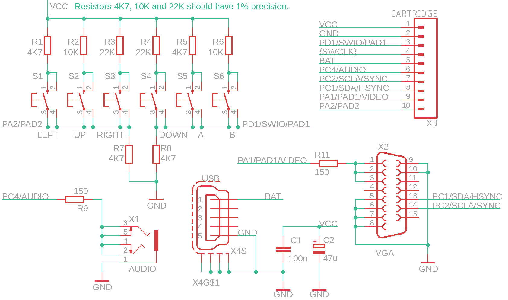
Cartridge:
![]()
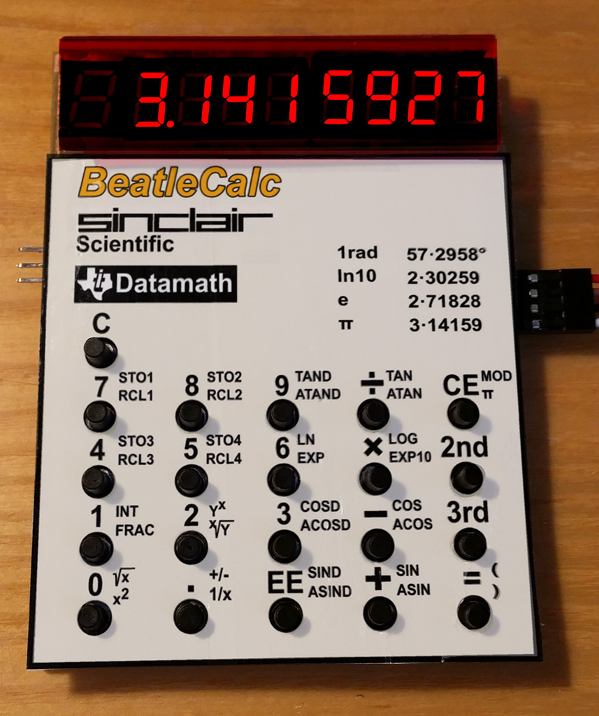
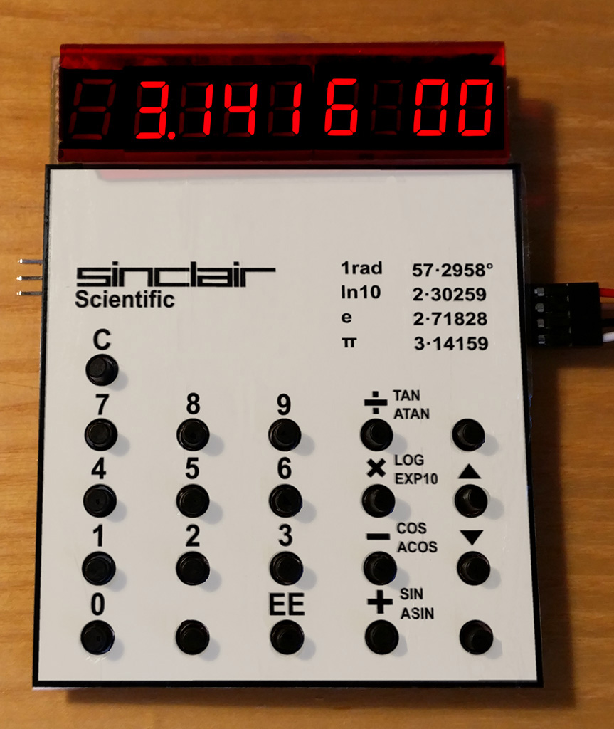
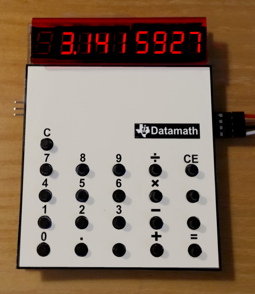
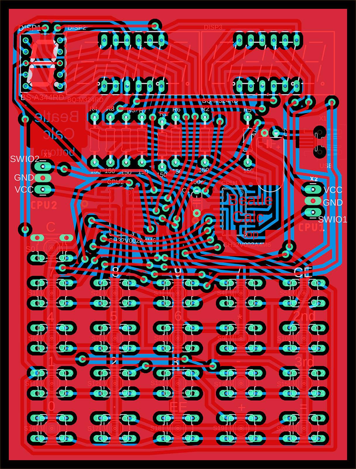
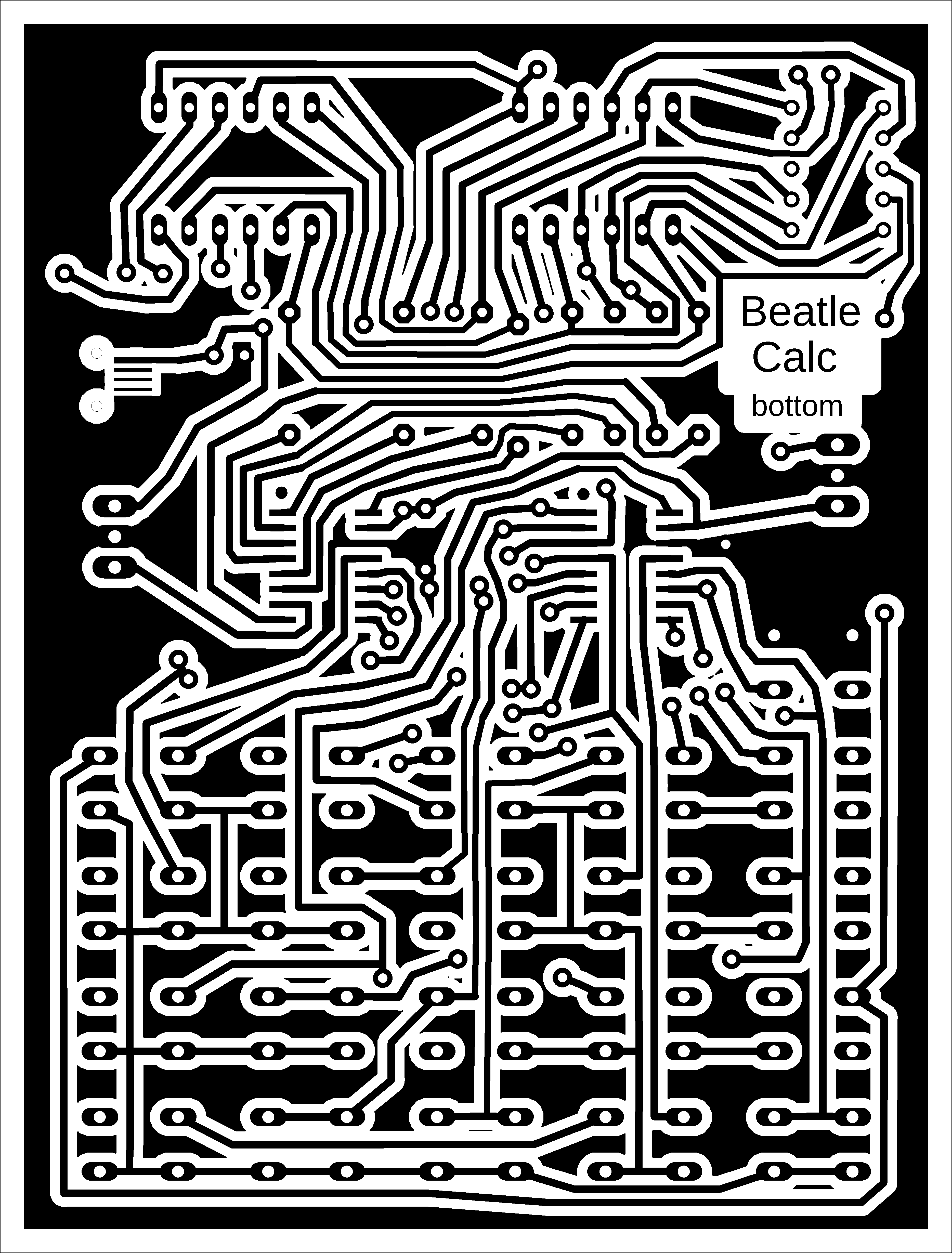
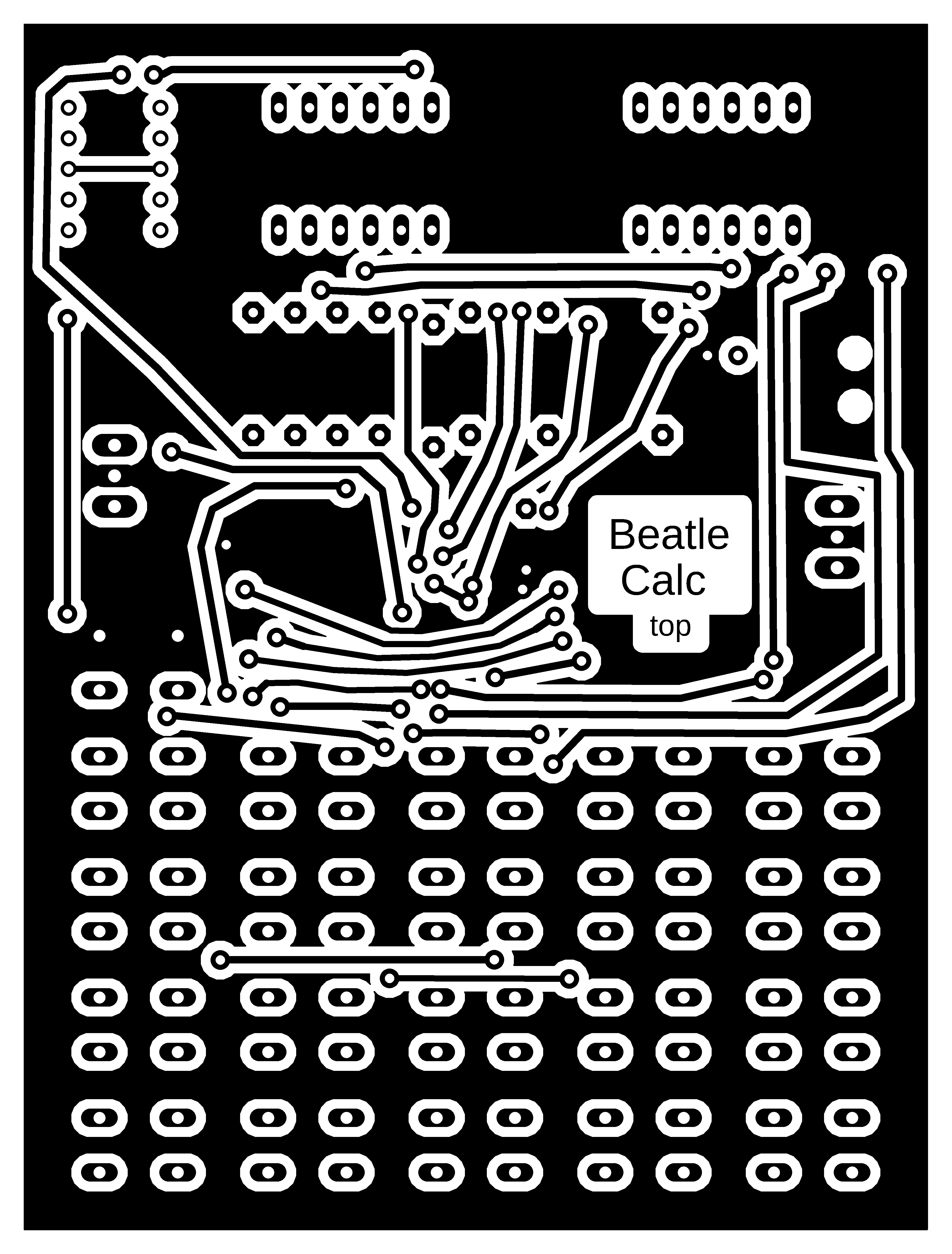
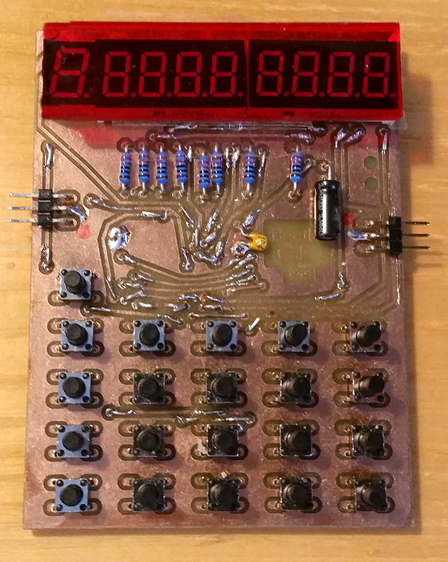
BeatleCalc is a minimalist scientific calculator, supplemented with emulators of calculators Sinclair Scientific (1974, TMC0805 processor) and Texas Instruments TI-2500 Datamath (1972, TMS0803 processor). The calculator uses BCD code internally, so it does not suffer from the inaccuracies of binary representation of decimal numbers. It calculates internally with an accuracy of 13 digits. The exponent ranges from -99 to +99. It includes calculations of direct and inverse trigonometric functions, in radians and degrees, natural and decimal logarithmic and exponential functions, powers and roots. It prefers operation priority, and parentheses can also be used. Numbers can be stored in 4 memory registers, which retain their value even when the power is turned off.
Switching the calculator mode between emulation or BeatleCalc calculator:
Press and hold the number 1 to 3: 1 selects the default BeatleCalc calculator, 2 selects Sinclair Scientific emulation, 3 selects Datamath emulation.
Press the C button briefly. This will reset the calculator.
Release the number 1 to 3 key. While you hold the key, the selected mode text will appear on the display: "CALCUL" is the default BeatleCalc calculator, "SINCLAIr" is Sinclair Scientific emulation, and "DATAMATH" is Datamath emulation.
Controls for emulated calculators can be found in the relevant calculator manuals. Please note that the Sinclair calculator uses RPN reverse logic - you must first enter the number and then the desired operation (typically '+' is used to insert a number into the stack). Emulators use only some of the calculator buttons - the layout of the buttons used can be seen in the pictures of the calculator labels.
BeatleCalc calculator functions:
STO1..STO4 ... Stores the number on the display in memory registers 1 to 4. The number is stored in the flash memory of the second CPU2 processor and remains available even after the power is turned off.
RCL1..RCL4 ... Displaying a number from memory registers 1 to 4.
CE ... Clearing the last digit or turning off the error indicator. If an unedited number is displayed, the calculator switches to edit mode.
2nd, 3rd ... Selection of alternative functions. An indicator appears at the first position on the display (2nd=upper line, 3rd=lower line).
= ... Calculation of the expression. Repeated pressing repeats the last operation with the last operand.
EE ... Exponent input mode. If an unedited number is displayed, the calculator enters exponent edit mode. Press the decimal point key to enter mantissa edit mode.
LOG, EXP10 ... Logarithmic and exponential functions with a decimal base.
LN, EXP ... Logarithmic and exponential functions with a natural base.
TAN, ATAN, SIN, ASIN, COS, ACOS ... Trigonometric functions calculated in radians.
TAND, ATAND, SIND, ASIND, COSD, ACOSD ... Trigonometric functions calculated in degrees.
Notes on construction:
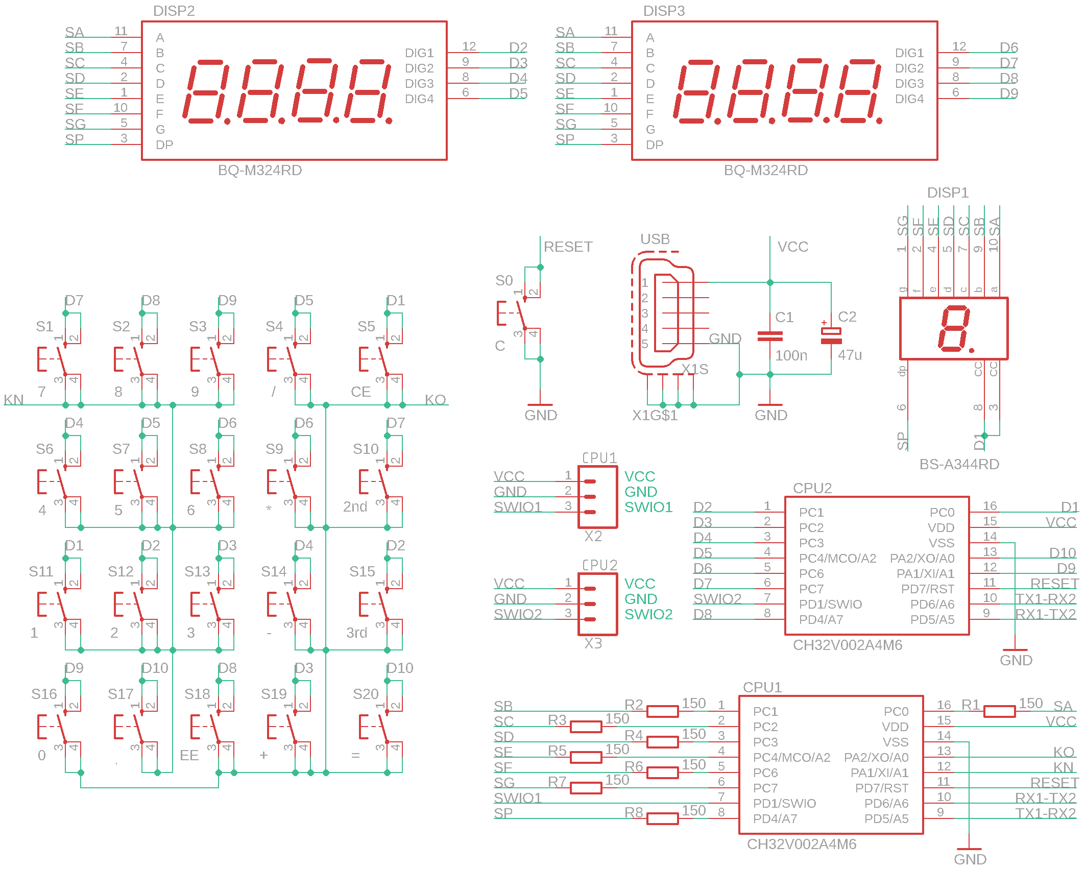
Two CH32V002A4M6 processors were used in the calculator. The reason for this choice (apart from the low price) is that they are easy to solder, which is also suitable for beginners. The CPU1 processor is the main processing unit. The CPU2 processor controls the display multiplexer and is used to store the configuration and memory registers. The photos show a prototype of the calculator – I focused primarily on the calculator software, not the design, so I recommend choosing your own calculator design. A printed circuit board can be used as the top cover of the calculator. For the prototype, I printed the label on paper, covered it with transparent adhesive tape on both sides, and cut out the holes for the buttons with a skin punch. I recommend covering the display with red Plexiglas, otherwise it may be difficult to read in bright light. The capacitors should be soldered horizontally so that they do not interfere with the top cover. I used a 1-digit LED display as the digit in the first position. You do not have to use it, because only the sign of the number and the indicators for the 2nd and 3rd buttons (segments A, D, and G) are displayed in this position. You can replace the digit display with a flat red LED connected between signals D1 and SG. The 2nd and 3rd indicators are not necessary. I did not solve the power supply issue in the prototype. It is also possible to use, for example, a 3.7V battery with a charging circuit. A CR2032 battery may not be powerful enough, as the display may have a high power consumption.
The calculator firmware consists of two parts. In the ch32\DEVICE\BeatleCalc folder, you will find the main executive firmware, which you will upload to the CPU1 processor (e.g., using the WCH-LinkE programmer: https://pajenicko.cz/usb-programator-a-debug-adapter-wch-link). The ch32\DEVICE\BeatleCalc_CPU2 folder contains the firmware for the second processor, CPU2. Until the firmware is loaded into both processors and communication between them is working, the display will remain dark. If you need to find a malfunction, use the ch32\DEMO\LED program, in which you will enter the appropriate pins and use the control LED to check whether the signals are OK.
Note: Calculator emulation was verified using the emulator https://static.righto.com/calculator/sinclair_scientific_simulator.html by Ken Shirriff. No physical calculators were available to verify functionality, so it is possible that the calculators' functions may not correspond exactly to the original.
>>> Source codes and all necessary documentation can be found in the CH32LibSDK library in the ch32\DEVICE\ folder. https://github.com/Panda381/CH32LibSDK/tree/main/ch32/DEVICE <<<
![]()
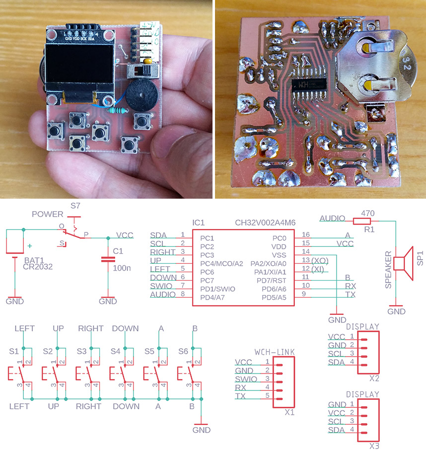
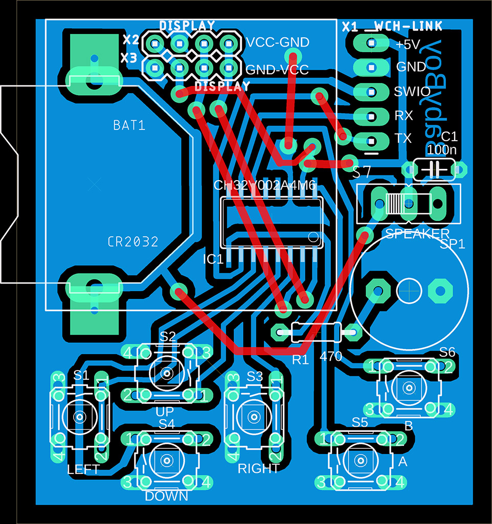
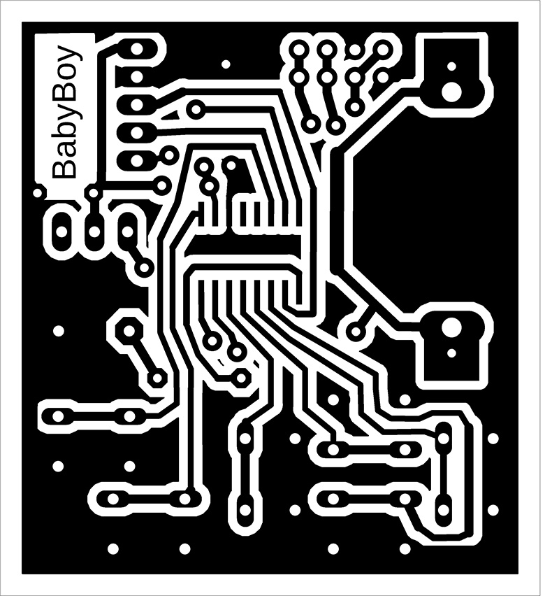
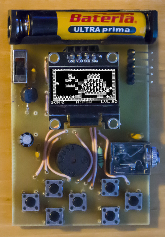
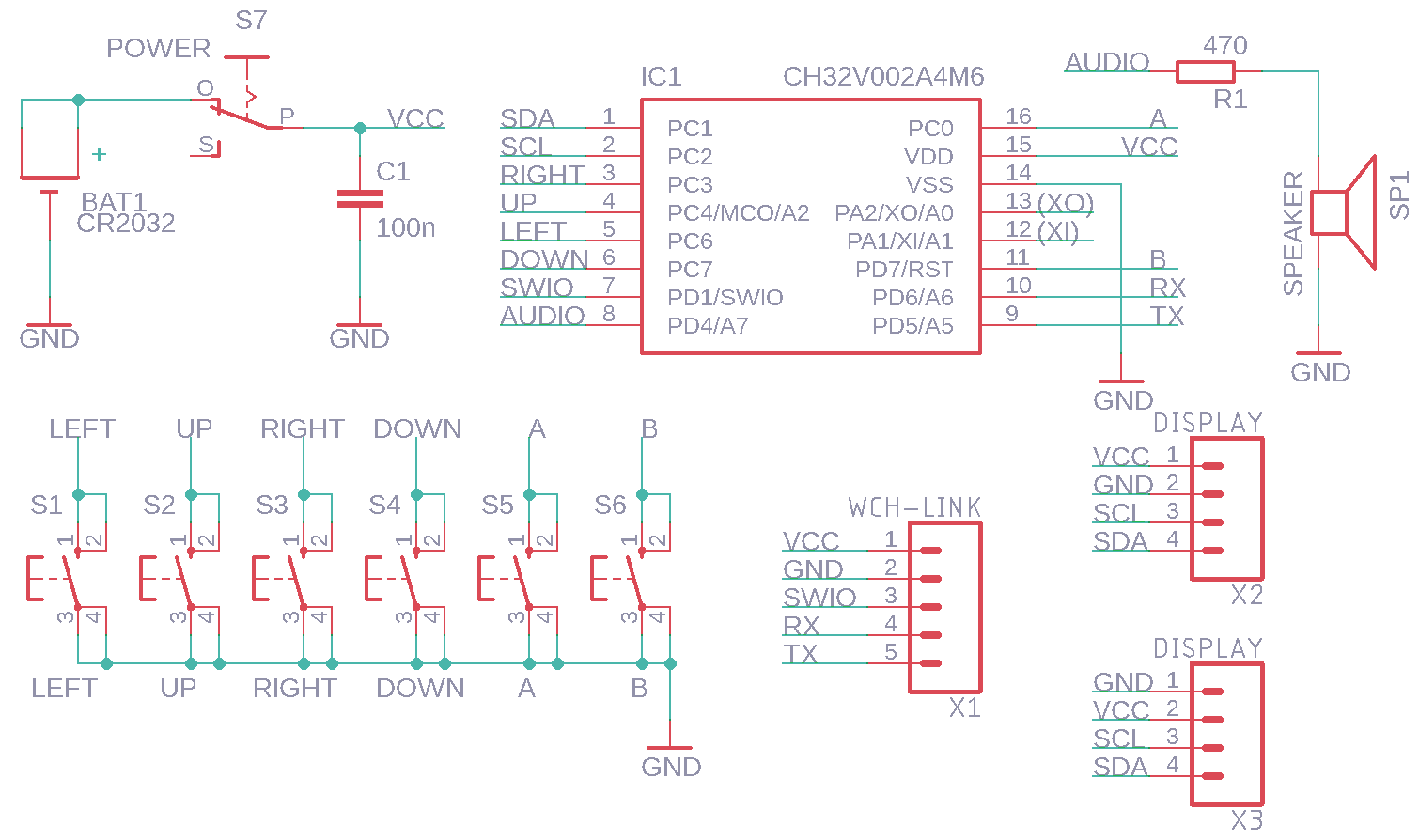
BabyBoy is the simplest game mini-console with 6 buttons, an inexpensive CH32V002A4M6 processor (price 10 cents), a built-in speaker, and 128x64 pixel black-and-white OLED I2C display with an SSD1306 controller. The console is powered by a CR2032 battery, or it can be powered by an external 3.3V source via the programming connector. Thanks to simplifications and the easy soldering of the processor in the SOP16 package with a pin pitch of 1.27mm, the console is primarily intended for beginners as a kit for their first introduction to electronics.
Pay attention to the pin layout on the display – there are usually two versions, with the pin order VCC-GND-SCL-SDA or GND-VDD-SCL-SDA. I used two pin headers on the circuit board for both display versions so that I could change the displays and insert them into the correct position. Note: Resistor R1 is possibly unnecessarily high (this is to reduce power consumption). Consider reducing its value or even omitting it.
BabyBoy does not include an SD card. Programs must be uploaded to the processor using the WCH-LinkE programmer (available here, for example: https://pajenicko.cz/usb-programator-a-debug-adapter-wch-link).
![]()
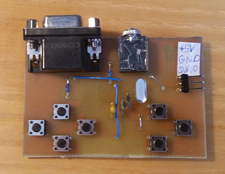
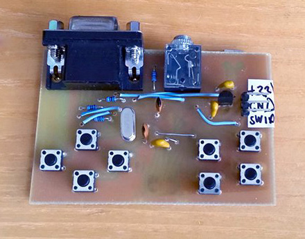
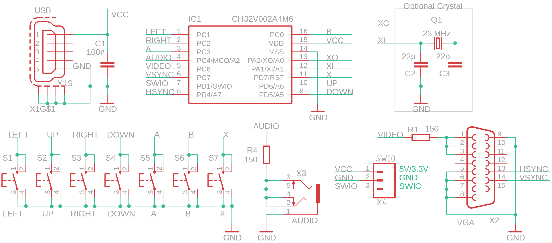
BabyPad is a mini game console with 7 buttons, with an inexpensive CH32V002A4M6 processor (costing 10 cents), 25 MHz crystal (optional), audio output, and VGA mono B&W output to a monitor. The crystal and associated capacitors are not required - if the software detects that the crystal is not available, it will use the internal HSI oscillator, tuned to a frequency close to 25 MHz. In this case, the image will be slightly noisy, but still usable - it depends on the monitor used how well it handles image stabilization. Slight image disruption may occur even when using a crystal - this is due to software image generation. BabyPad uses a processor in an SOP16 package with a pin pitch of 1.27 mm, which makes soldering easy even for beginners. Together with its simple design (and the option of not installing a crystal), it is primarily intended for beginners as a kit for their first introduction to electronics.
BabyPad does not include an SD card. Programs must be uploaded to the processor using the WCH-LinkE programmer (available here, for example: https://pajenicko.cz/usb-programator-a-debug-adapter-wch-link).


![]()
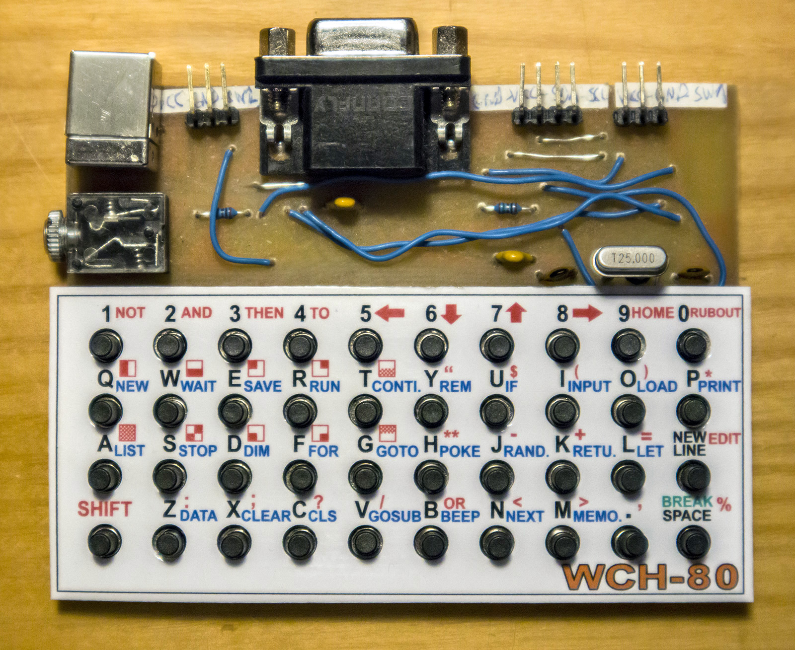
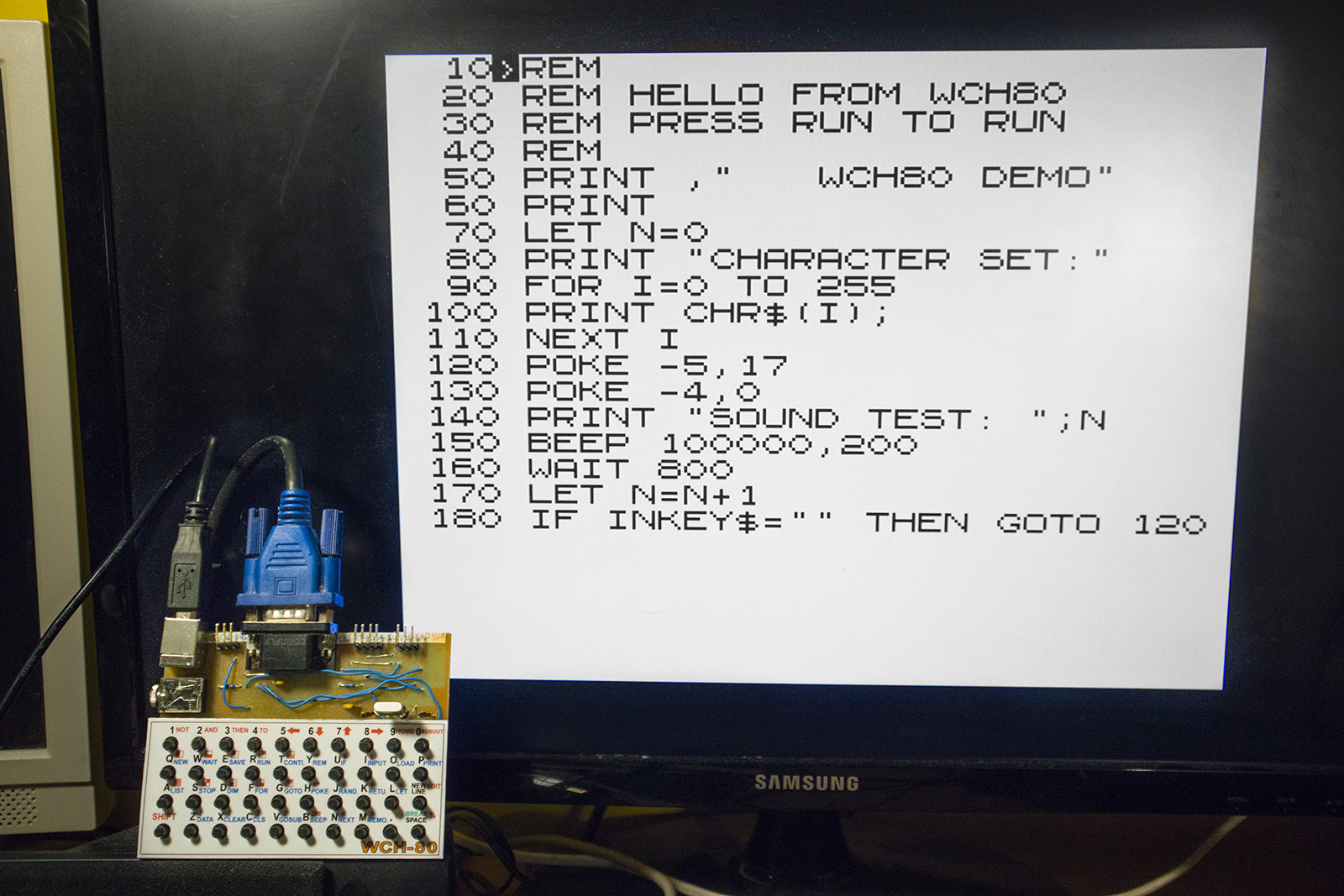
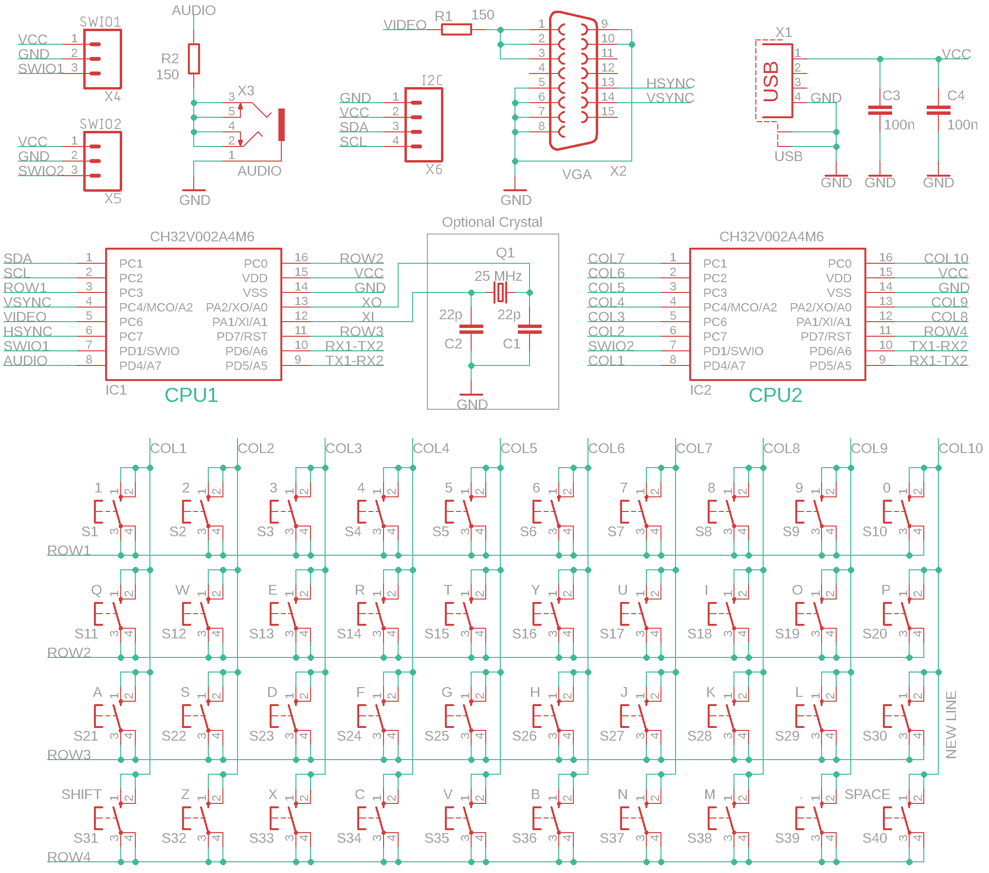
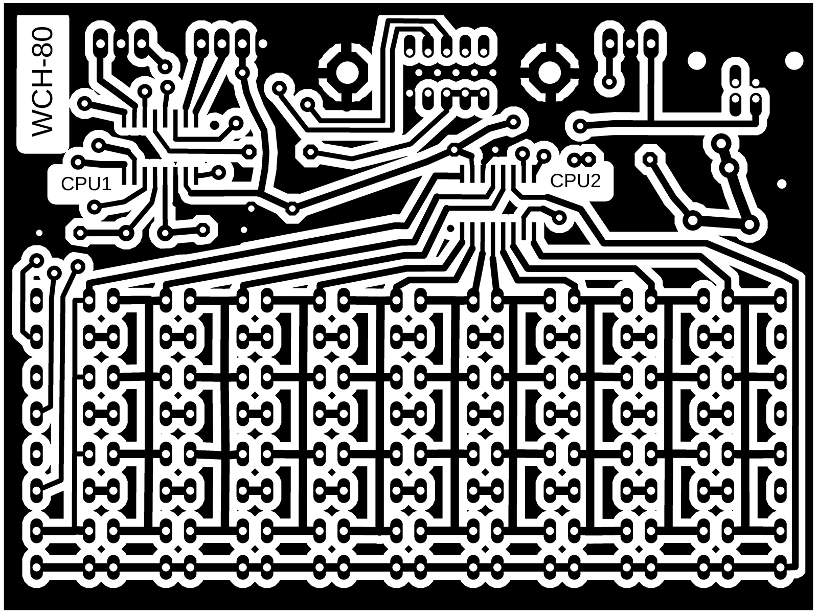
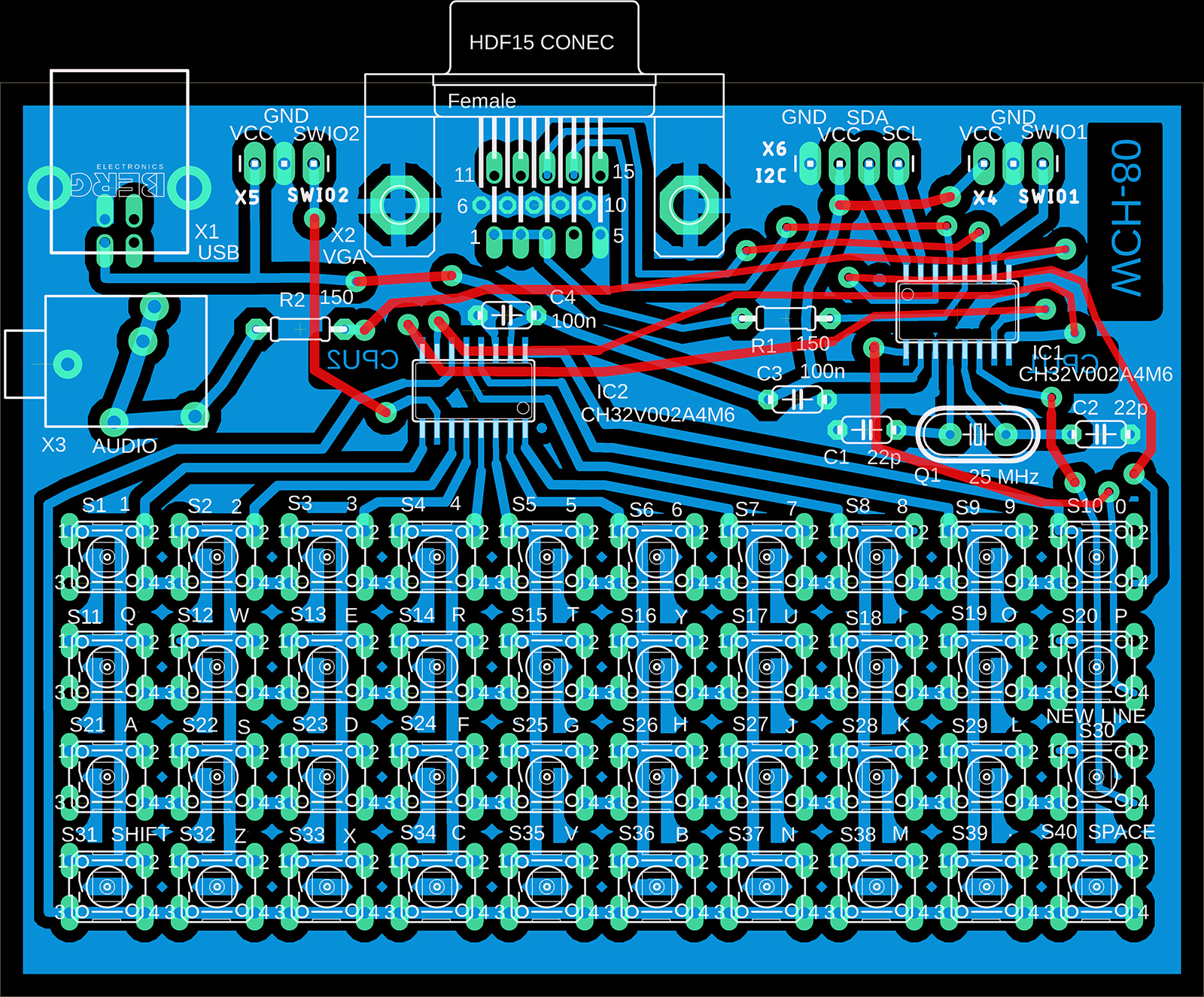
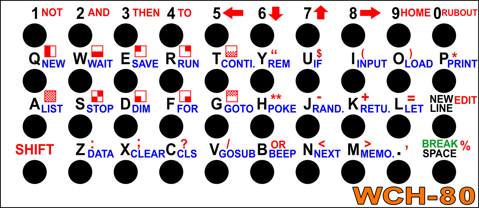
The BabyPC - WCH80 is an inexpensive mini-computer with two CH32V002 processors, created based on the ZX80 computer. It is not an emulator; the computer does not emulate the ZX80 computer's ROM, nor does it emulate Z80 machine instructions. It was created as a completely independent computer with the BASIC80 programming language and VGA monitor output, only replicating the ZX80's functionality as closely as possible. It uses a CH32V002A4M6 processor, which, thanks to its large 1.27 mm pin pitch, is suitable for easy soldering even for novice designers. Together with other THT components, the WCH80 is particularly suitable as a kit for novice designers. The built-in BASIC80 programming language is used to familiarize users with computer programming and to try out how programmers programmed in the 1980s.
The computer does not contain a storage medium for saving programs. Your own programs can be saved directly to the processor's flash memory. There are 14 memory slots available, i.e. 14 places to store your own programs, numbered 0 to 13. Slot 0 is located in the main CPU1 processor. When stored in slot 0, data variables are also stored along with the program (more precisely, only the first half of the memory with variables). Slot 0 is automatically loaded into the program memory when the computer is turned on. Memory slots 1 to 13 are located in the second processor, CPU2. All slots allow the entire memory with the program to be stored, except for the last slot 13, which is only half the size.
After initial programming, the processors contain 28 sample programs and games written in BASIC80. Once the processors have been programmed, the programmer is no longer needed, but it can be useful if you want to back up the contents of the processors to a PC or if you want to change program versions. Using slot 0, programs can also be transferred between the processors' memory backups by copying between the CPU1 and CPU2 processors.
In addition to the BASIC80 firmware, games and programs written in C can also be uploaded to the computer using a programmer. There are 25 sample games available. The games can be found in the CH32LibSDK library. However, it is important to remember that reprogramming the CPU1 processor will also overwrite the contents of slot 0. The contents of slots 1 to 13 in CPU2 will not change when games are loaded. For games in C code, the following keys are usually used for control: 8, F=right, 7, E=up, 5, S=left, 6, D=down, A, space=action, B, NEW LINE=alternative action, X, P=info, Y, 0=back.
More details and supporting documents can be found on a separate page: www.breatharian.eu/hw/wch80/index_en.html or on GitHub: github.com/Panda381/WCH80.
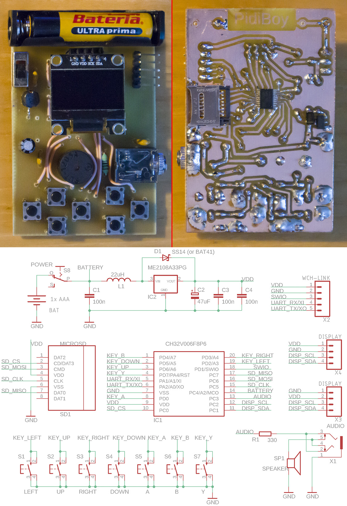
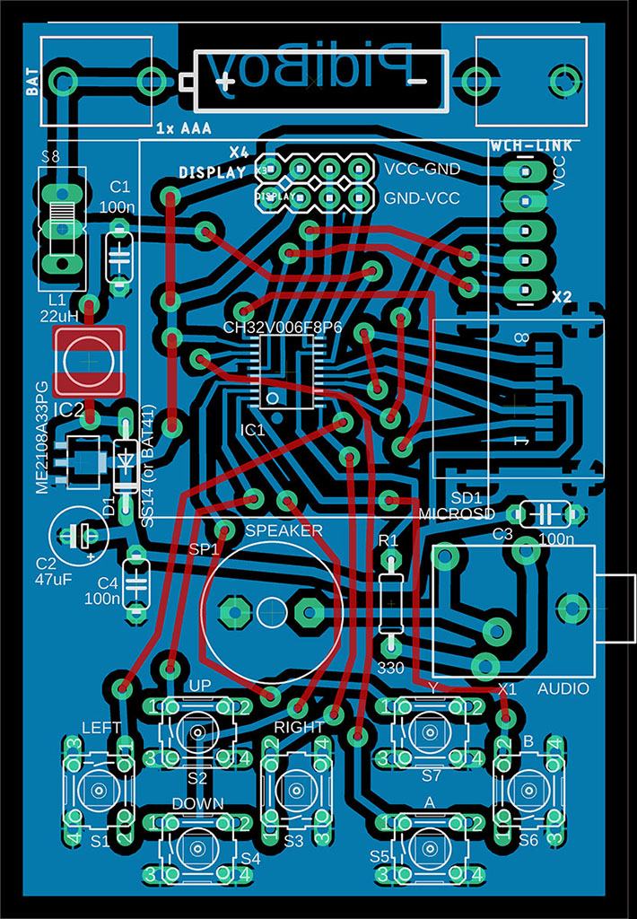
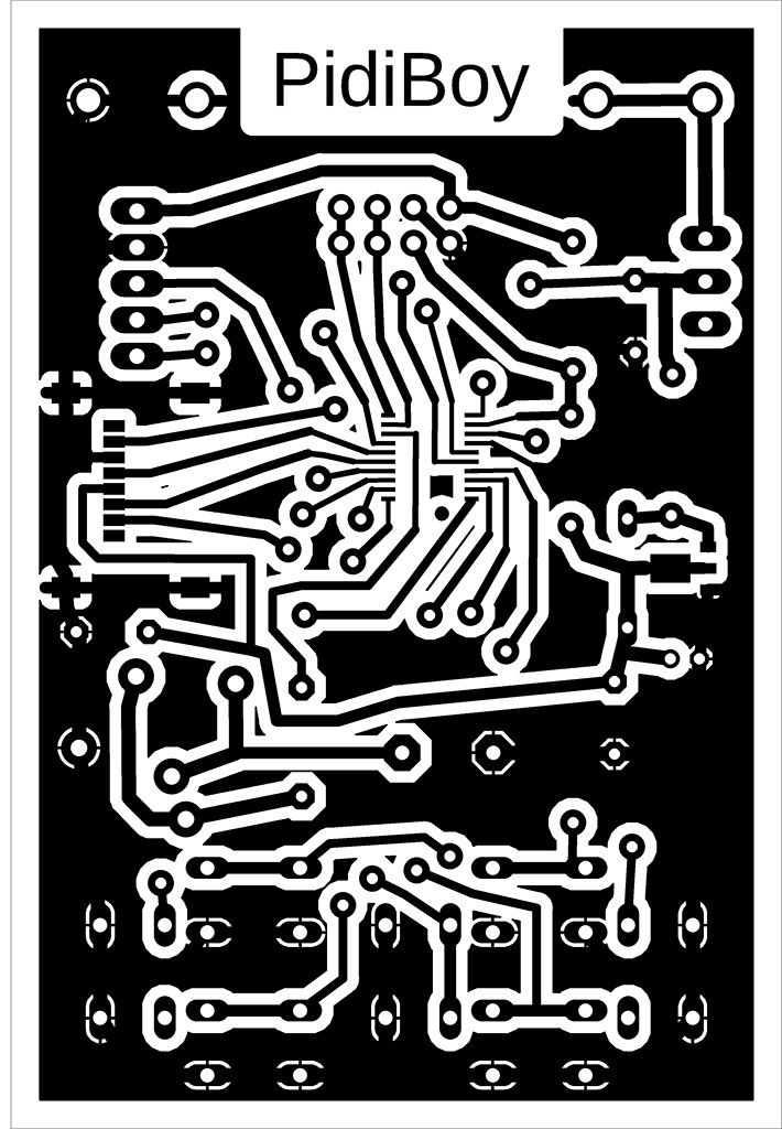
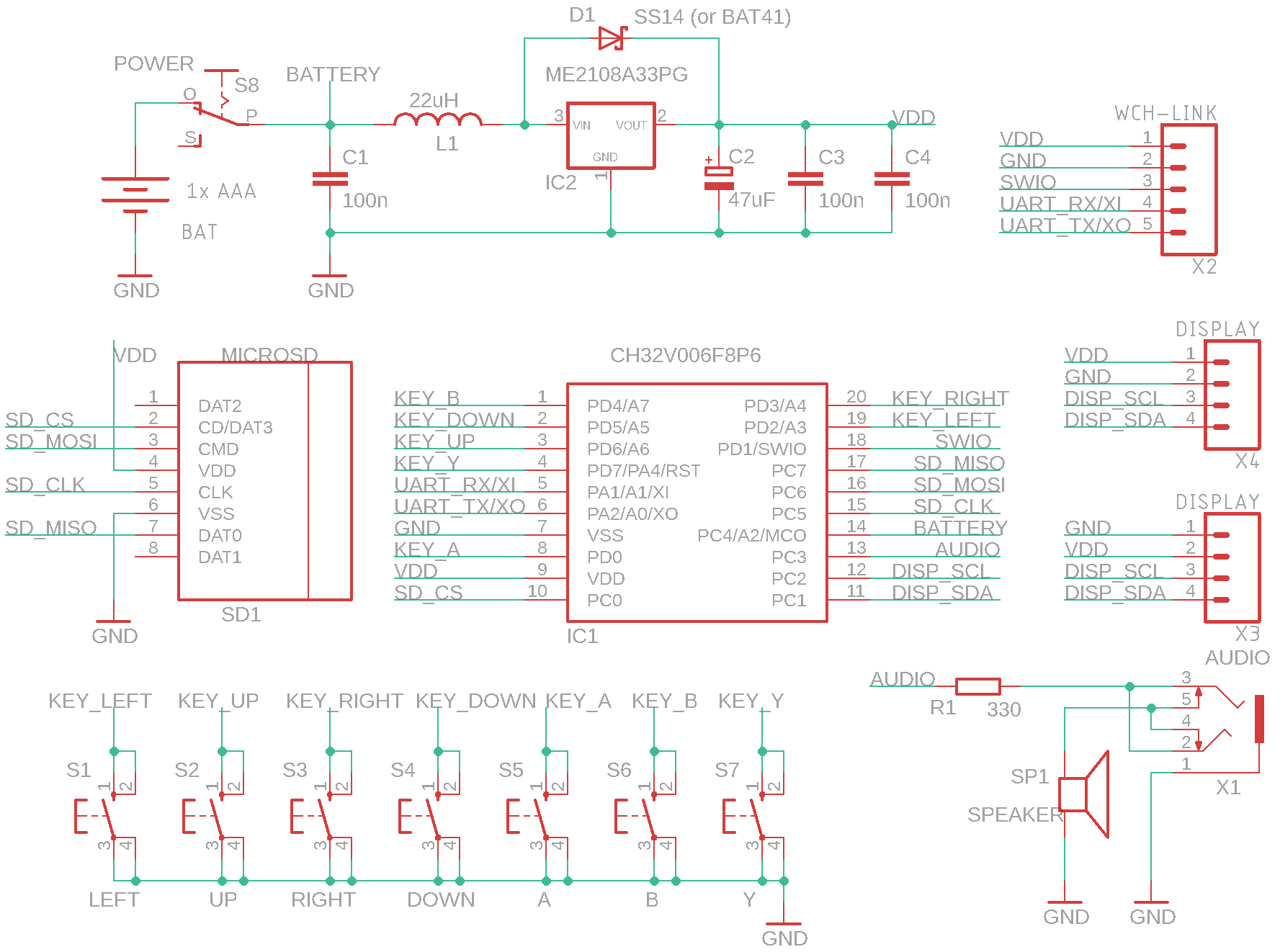
PidiBoy is a mini game console with 7 buttons, an inexpensive CH32V006F8P6 processor (costing 20 cents), a microSD card, a built-in speaker, audio output, and 128x64 pixel black-and-white OLED I2C display with an SSD1306 controller. The console is equipped with an ME2108A33PG step-up voltage converter with a 3.3V output and can therefore be operated from 1 or 2 AA or AAA batteries in the voltage range of 1.1V to 3.3V, or the console can be powered by an external 3.3V source via the programming connector. Programs can be run from an SD card using a boot loader, which loads the program into the processor's flash memory. Boot loader controls: up/down arrows - move the cursor by 1 item, left/right arrows - move the cursor by 1 page, A - start program or change folder, B - display voltage or move to parent folder, Y - run program located in flash memory. Pay attention to the pin layout on the display – there are usually two versions, with the pin order VCC-GND-SCL-SDA or GND-VDD-SCL-SDA. I used two pin headers on the circuit board for both display versions so that I could change the displays and insert them into the correct position.
Programs compiled for PidiBoy contain a boot loader. Writing to flash memory using a programmer writes both the program and the boot loader. Pressing the Y button (or resetting with an SD card inserted) launches the boot loader, allowing you to select the program to be run from the SD card. The boot loader ensures that the program is loaded from the SD card into the flash memory. Another program can be loaded by pressing Y or by resetting with an SD card inserted. If no SD card is inserted after resetting, the boot loader will not start, but the program in the flash memory will start immediately. The program in the flash memory can also be started from the boot loader by pressing the Y button.
BIN and ELF files are provided with a checksum during compilation using the LoaderCrc program. Checksum is used by the boot loader to check the application in flash memory. If you want to load the application into flash memory using WCH-LinkUtility, you must use a BIN file and not a HEX file, because the generated HEX file does not have a checksum.
![]()
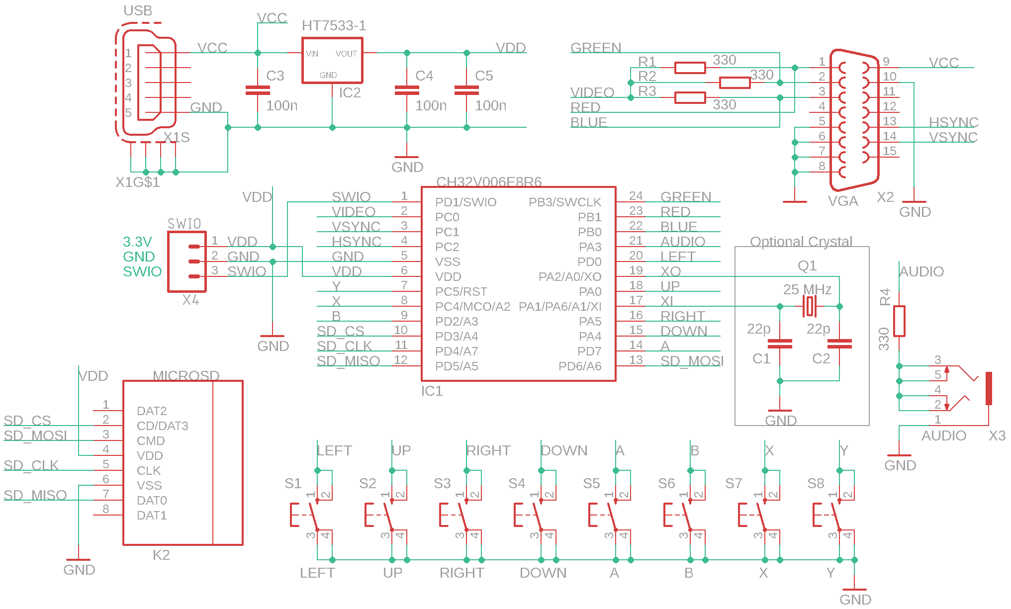
PidiPad is mini game console with 8 buttons, with a cheap CH32V006E8R6 processor (costing 20 cents), 25 MHz crystal (optional), microSD card, audio output, and VGA output to monitor. The crystal and associated capacitors do not need to be used – if the software detects that the crystal is not present, it will use the internal HSI oscillator, tuned to a frequency close to 25 MHz. In this case, the image will be slightly noisy, but still usable - it depends on the monitor used how well it handles image stabilization. Slight image disruption may occur even when using a crystal - this is due to software image generation.
Programs compiled for PidiPad contain a boot loader. Writing to flash memory using a programmer writes both the program and the boot loader. Pressing the Y button (or resetting with an SD card inserted) launches the boot loader, allowing you to select the program to be run from the SD card. The boot loader ensures that the program is loaded from the SD card into the flash memory. Another program can be loaded by pressing Y or by resetting with an SD card inserted. If no SD card is inserted after resetting, the boot loader will not start, but the program in the flash memory will start immediately. The program in the flash memory can also be started from the boot loader by pressing the Y button.
 Boot loader - used to
run programs from an SD card.
Boot loader - used to
run programs from an SD card.
BIN and ELF files are provided with a checksum during compilation using the LoaderCrc program. Checksum is used by the boot loader to check the application in flash memory. If you want to load the application into flash memory using WCH-LinkUtility, you must use a BIN file and not a HEX file, because the generated HEX file does not have a checksum.


![]()
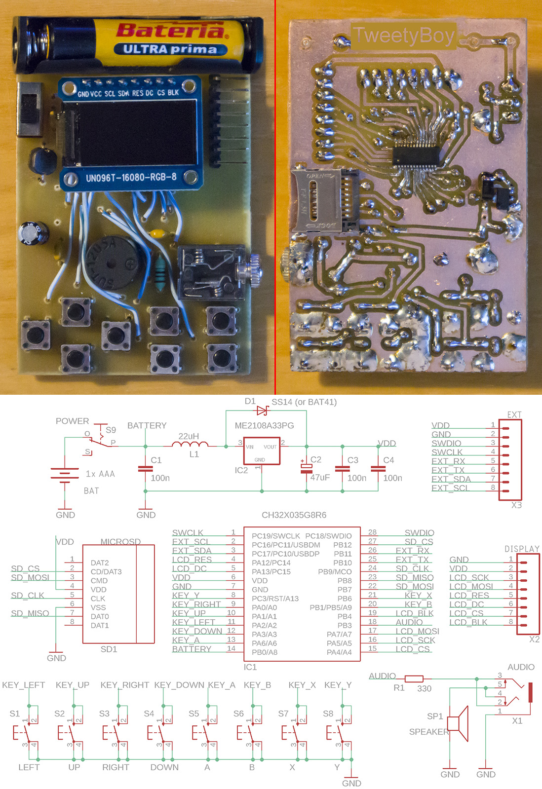
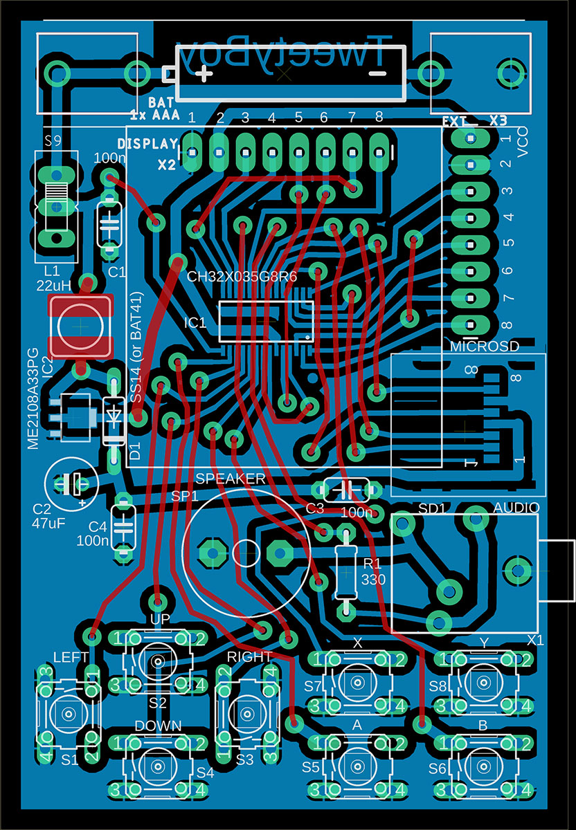
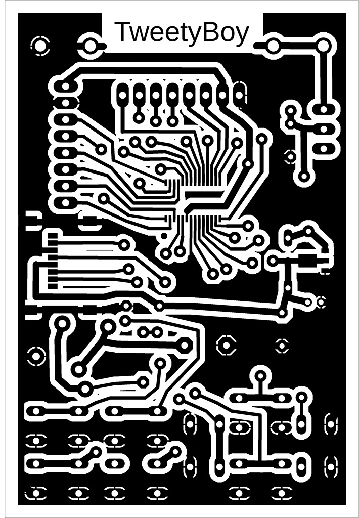
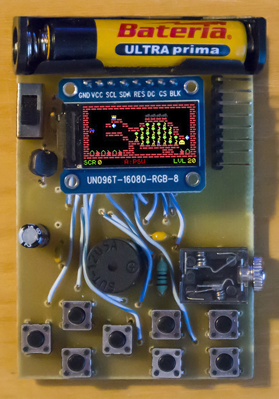
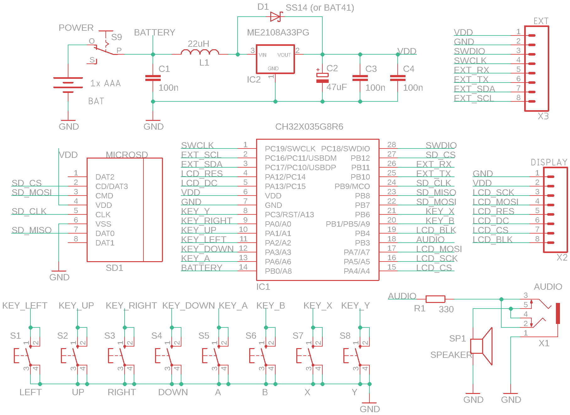
TweetyBoy is a mini game console with 8 buttons, a low-cost CH32X035G8R6 processor (price: 50 cents), a microSD card, a built-in speaker, audio output, and 160x80 pixel LCD SPI color display with an ST7735S controller. The console is equipped with an ME2108A33PG step-up voltage converter with a 3.3V output and can therefore be operated from 1 or 2 AA or AAA batteries in the voltage range of 1.1V to 3.3V, or the console can be powered by an external 3.3V source via the programming connector. Programs can be run from an SD card using a boot loader, which loads the program into the processor's flash memory. Boot loader controls: up/down arrows - move the cursor by 1 item, left/right arrows - move the cursor by 1 page, A - start program or change folder, B - display voltage, adjust display brightness, or move to parent folder, Y - start the program located in the flash memory.
The brightness of the LCD display can be adjusted from the boot loader by pressing the B button. The display brightness can be adjusted in 9 steps, from 1 to 9. Complete dimming of the display (level 0) is not possible to prevent the console from becoming uncontrollable. When powered by battery, it is recommended to keep the display brightness as low as possible to minimize battery consumption. The display has a power consumption of 0.5mA to 17mA from a 3.3V source, at brightness levels 1 to 9. Each 1-step decrease in display brightness represents a reduction in display power consumption by almost half. The default brightness value of 6 means a display consumption of 3mA. The processor consumption is about 6mA. However, this is the consumption from a 3.3V source. The battery consumption is about 3 times higher due to the step-up converter voltage transformation.
Programs compiled for TweetyBoy contain a boot loader. When writing a program to flash memory using a programmer, both the program and the boot loader are written. Pressing the Y button (or resetting with an SD card inserted) launches the boot loader, which allows you to select the program to be run from the SD card. The boot loader ensures that the program is loaded from the SD card into flash memory. Another program can be loaded by pressing the Y button or by resetting with the SD card inserted. If no SD card is inserted during the reset, the boot loader will not start, but the program in flash memory will start immediately. The program in flash memory can also be started from the boot loader by pressing the Y button.
BIN and ELF files are provided with a checksum during compilation using the LoaderCrc program. Checksum is used by the boot loader to check the application in flash memory. If you want to load the application into flash memory using WCH-LinkUtility, you must use a BIN file and not a HEX file, because the generated HEX file does not have a checksum.
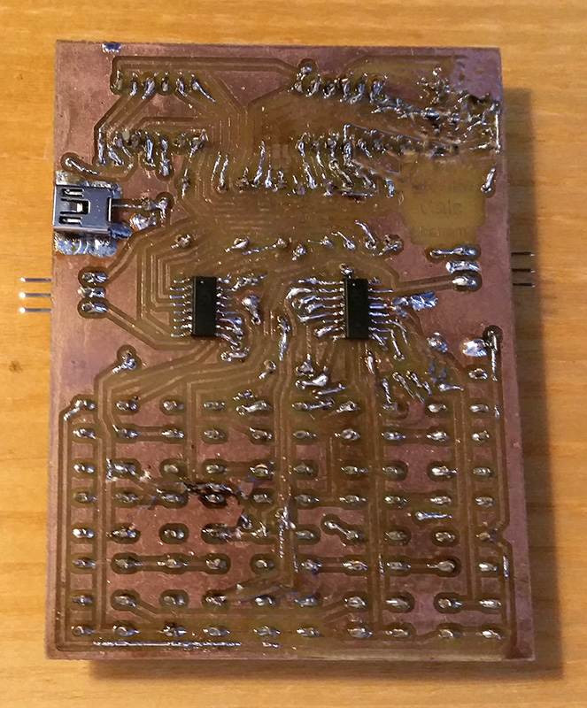
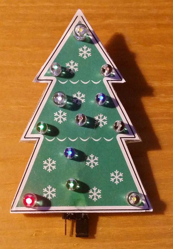
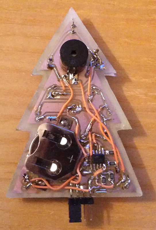
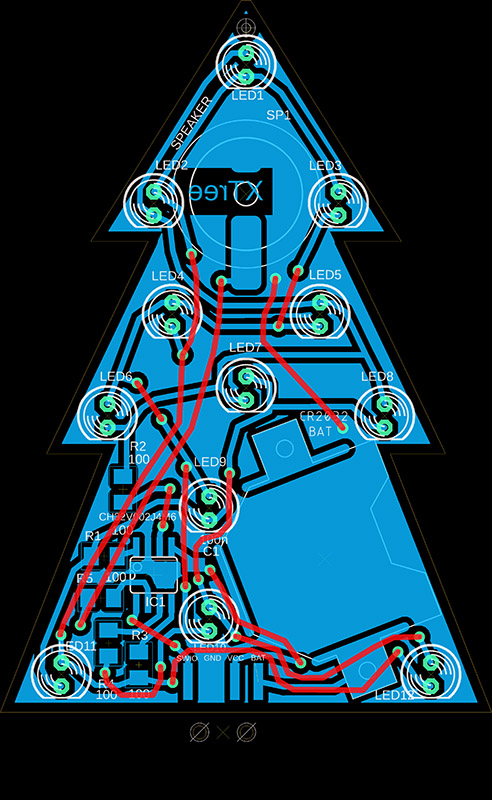
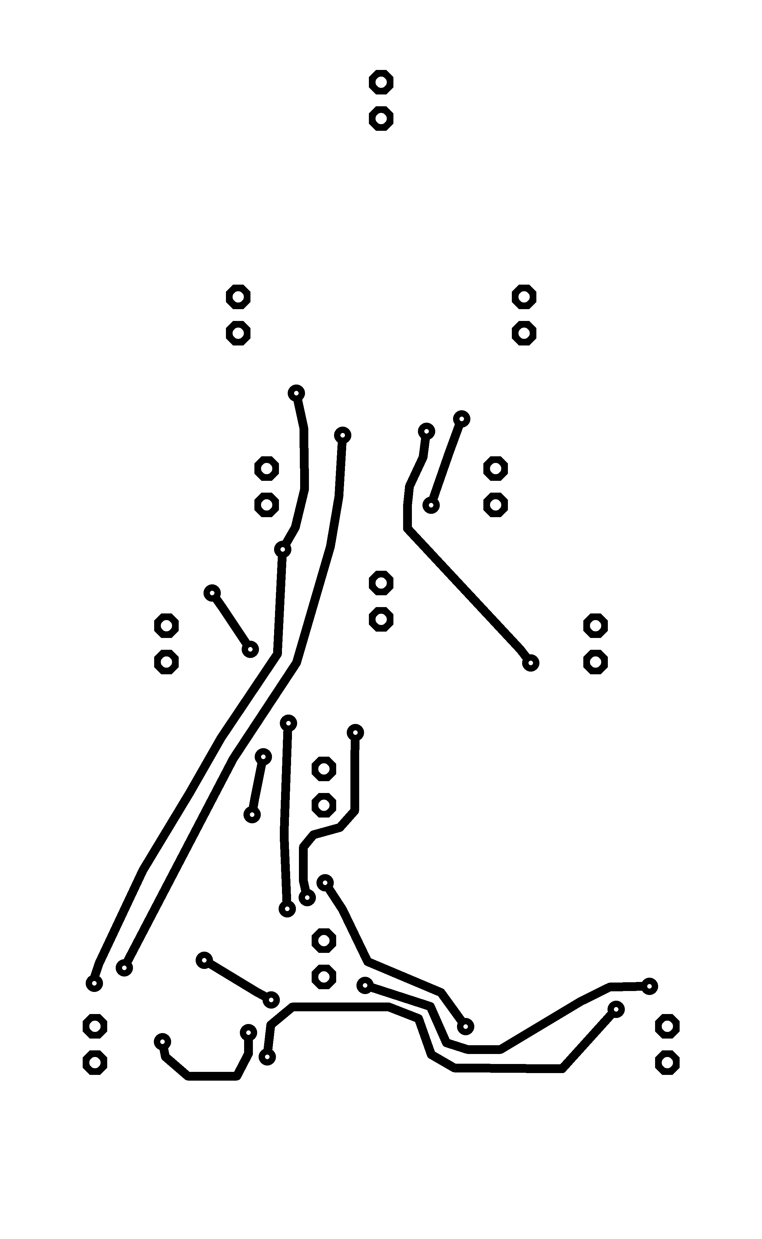
XTree is a Christmas tree-shaped pendant with a CH32V002J4M6 processor, 12 flashing LEDs, and a speaker that plays "Jingle Bells." XTree is powered by a CR2032 battery. A label with a picture of a Christmas tree and, optionally, a star is glued to the front. Only the LEDs are on the front; all other components are soldered to the back of the circuit board. The components used should be easy to solder, even for novice designers. On the bottom edge is a connector for programming the processor, which also serves as a switch - inserting the jumper on the right side of the connector turns XTree on. The jumper also represents the trunk of the tree. When turned off, the jumper can be inserted on the left side of the connector. High-brightness LEDs should be used, otherwise they may have low brightness. Matte LEDs would be more suitable, but they have lower brightness. Alternatively, reduce the resistor values. On the other hand, low LED brightness ensures lower battery consumption - the consumption is around 8mA. The sound from the speaker is not very loud, but it should be enough so that the music is not too distracting. In the prototype, I used wires instead of the top layer of the printed circuit board - I recommend using a double-sided printed circuit board, or even one with a printed image.
>>> The source codes and all necessary XTree documentation can be found in the CH32LibSDK library in the ch32\TOYS\XTree folder. https://github.com/Panda381/CH32LibSDK/tree/main/ch32/TOYS/XTree <<<


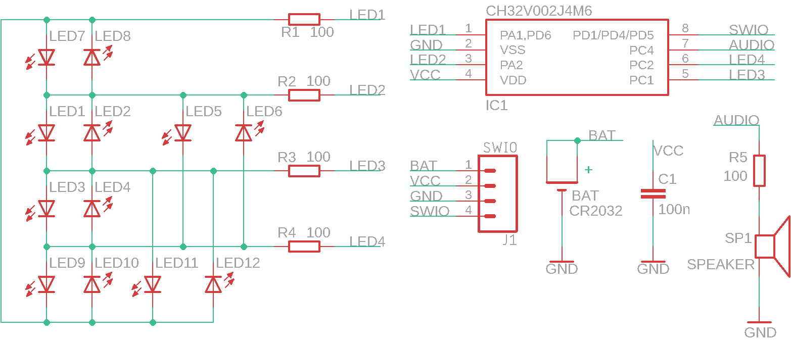
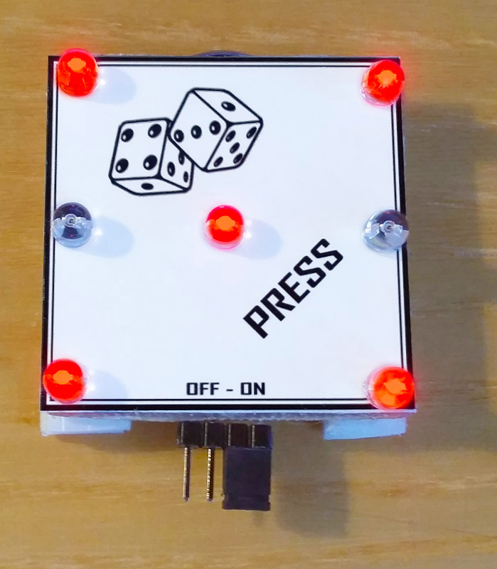
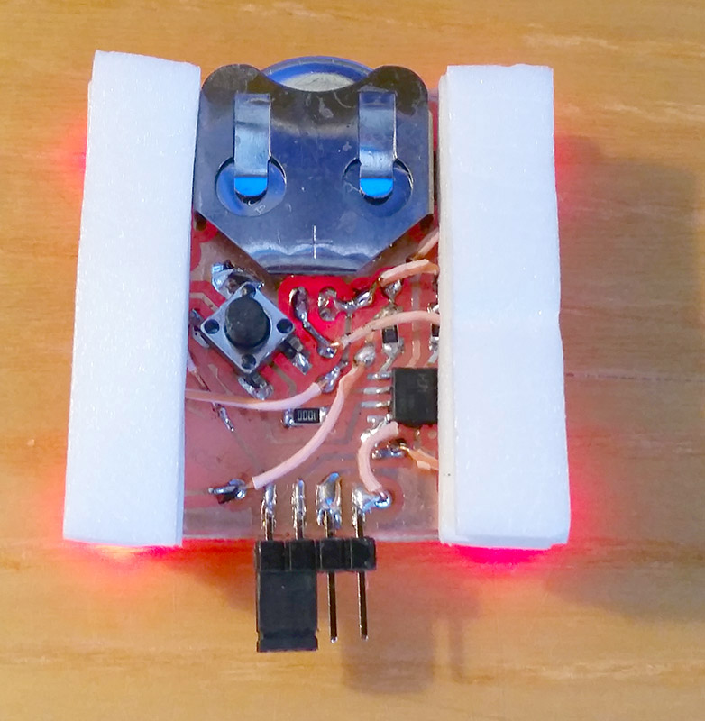
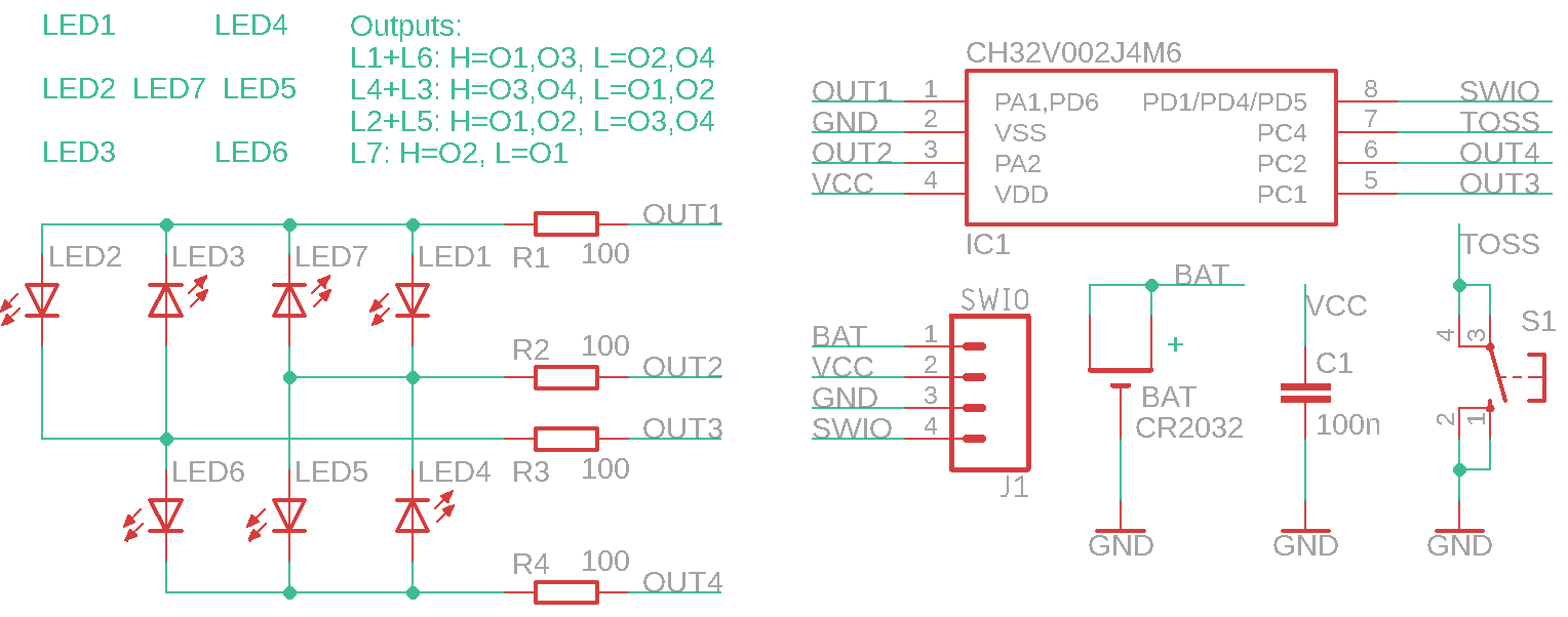
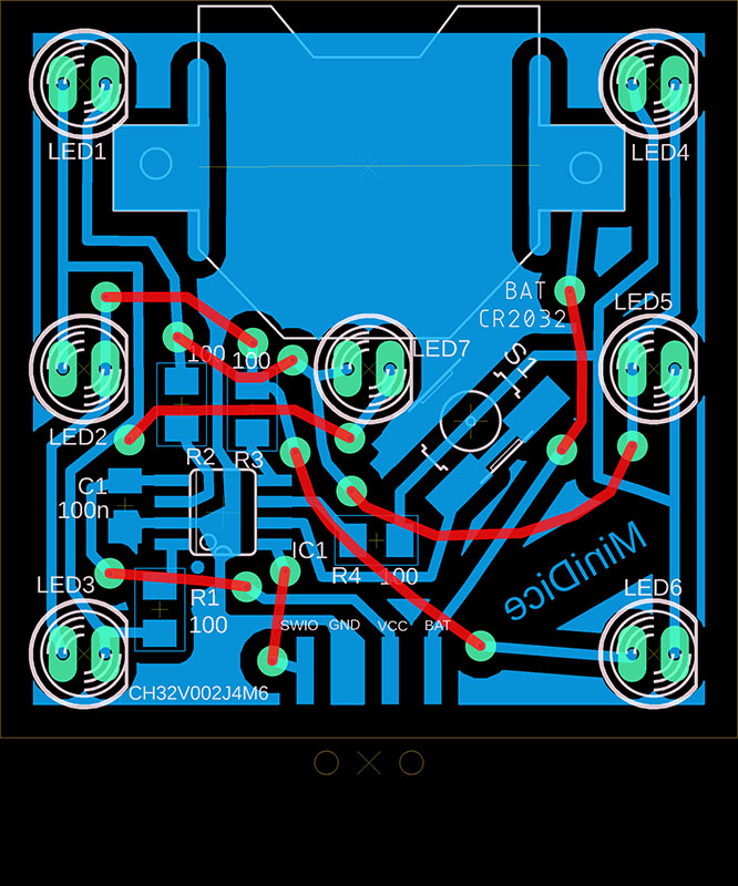
MiniDice is an electronic dice with 7 LEDs, a CH32V002J4M6 processor, and a CR2032 battery. The dice is activated by pressing it against the table - there is a microswitch on the bottom. A 4-pin pin header with a jumper serves as a power switch, and is also used to program the processor. However, it is not necessary to use the power switch. The dice automatically turns off 10 seconds after the last use and enters power-saving mode, when it consumes only 10uA from the battery. If you do not need to program the processor, you can remove the programming connector and connect the BAT and VCC pins. In power-saving mode, the battery should last 1 to 2 years. Alternatively, remove the battery if you are not going to use it for a long time.
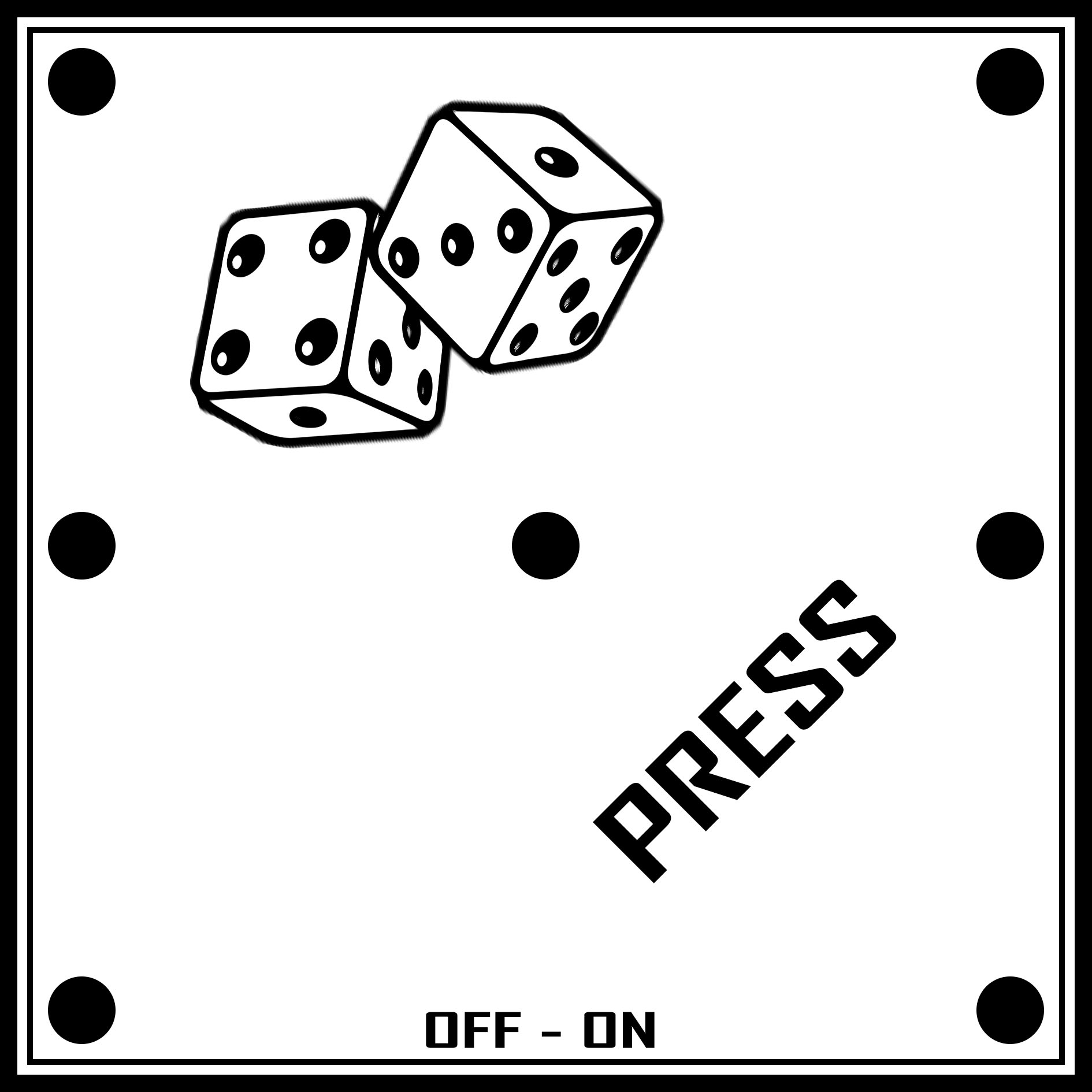
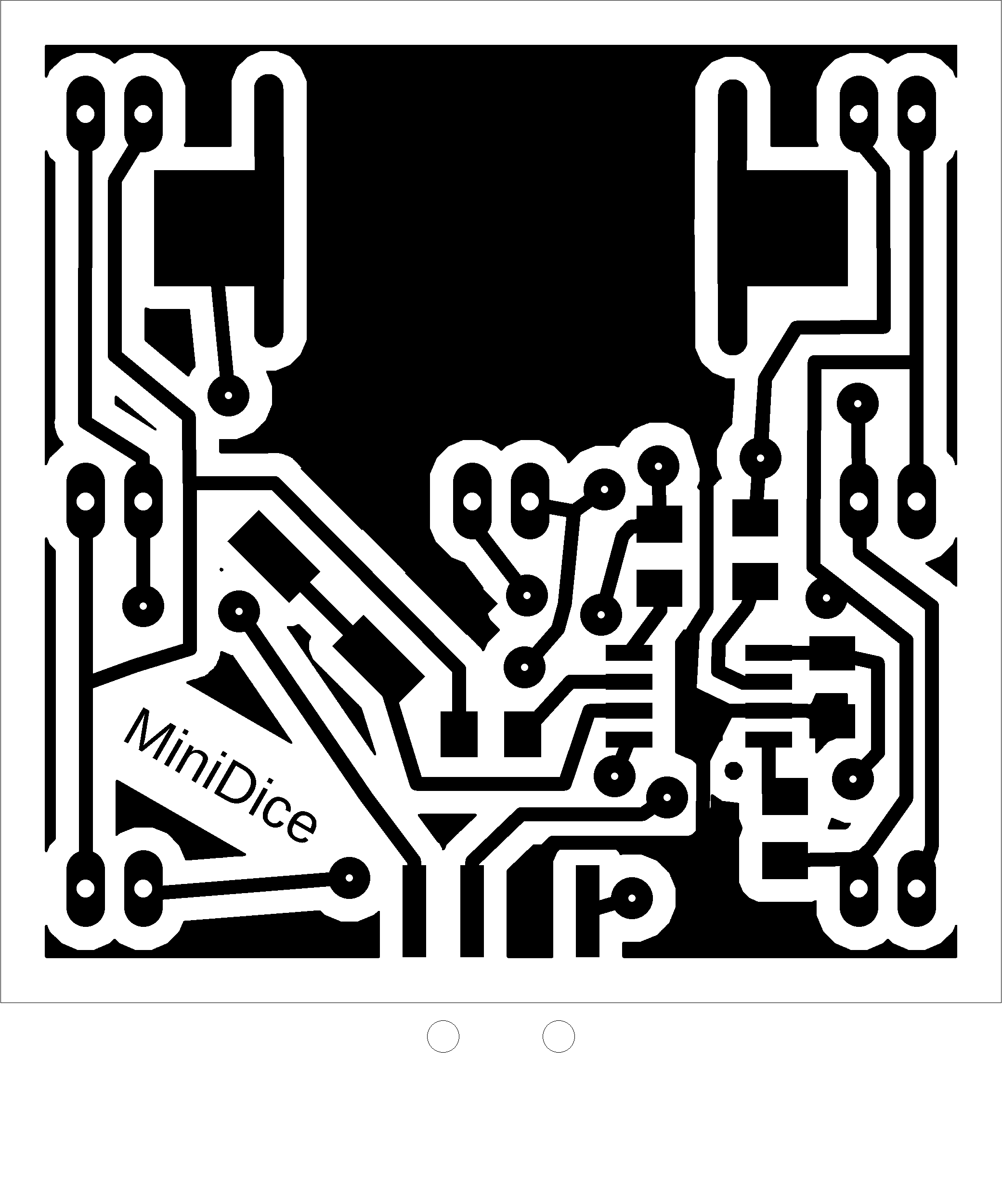
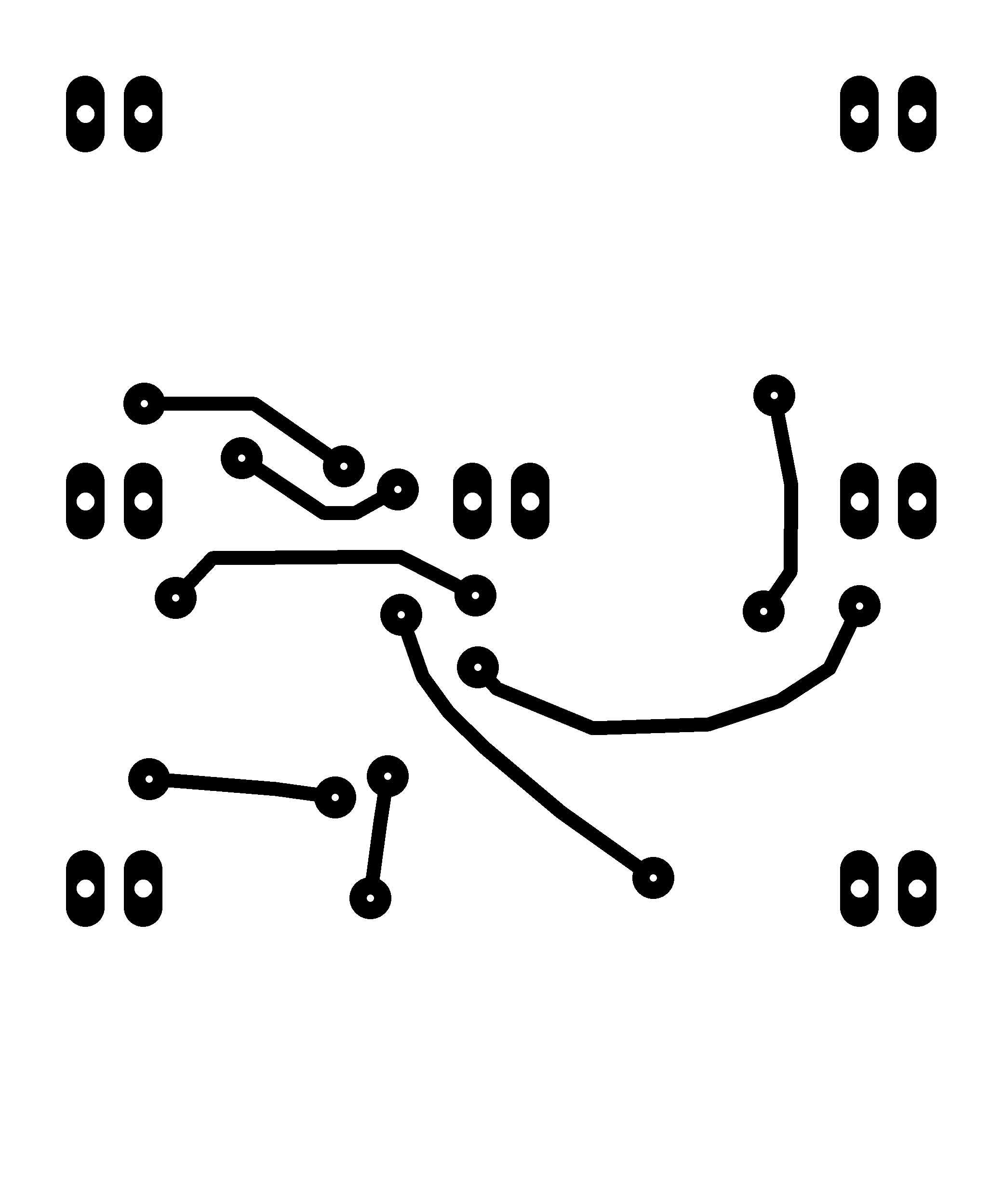
Only 7 LEDs are located on the top of the circuit board; all other components are soldered to the bottom of the circuit board. In the prototype, I used wires instead of one layer of printed circuit board. You will certainly use a double-sided printed circuit board. I used TS6604B-7.0 with a 3.5mm tactile length as the activation microswitch. Two layers of foam rubber are glued to the sides from below for cushioning, so that the dice stands upright on the table and can be easily pressed. I printed the top label on an inkjet printer, glued it on, and covered it with transparent adhesive tape. You will probably use printing on the printed circuit board. When soldering the battery holder, be careful not to short-circuit the middle LED - if necessary, bend the battery holder slightly in that spot. If the battery is too difficult to insert, bend the pressure springs of the battery holder.
>>> The source codes and all necessary MiniDice documentation can be found in the CH32LibSDK library in the ch32\TOYS\MiniDice folder. https://github.com/Panda381/CH32LibSDK/tree/main/ch32/TOYS/MiniDice <<<
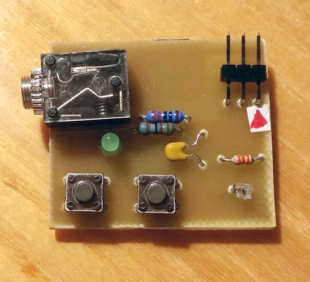
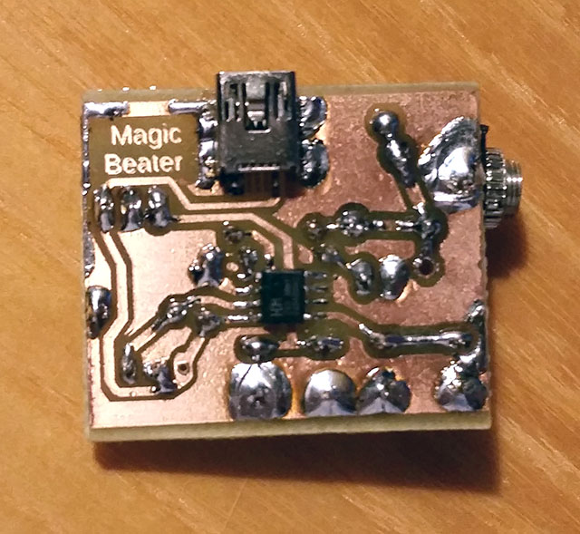
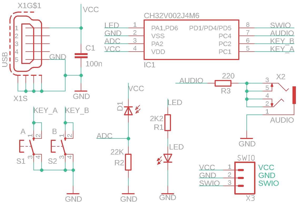
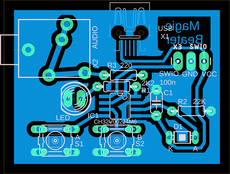
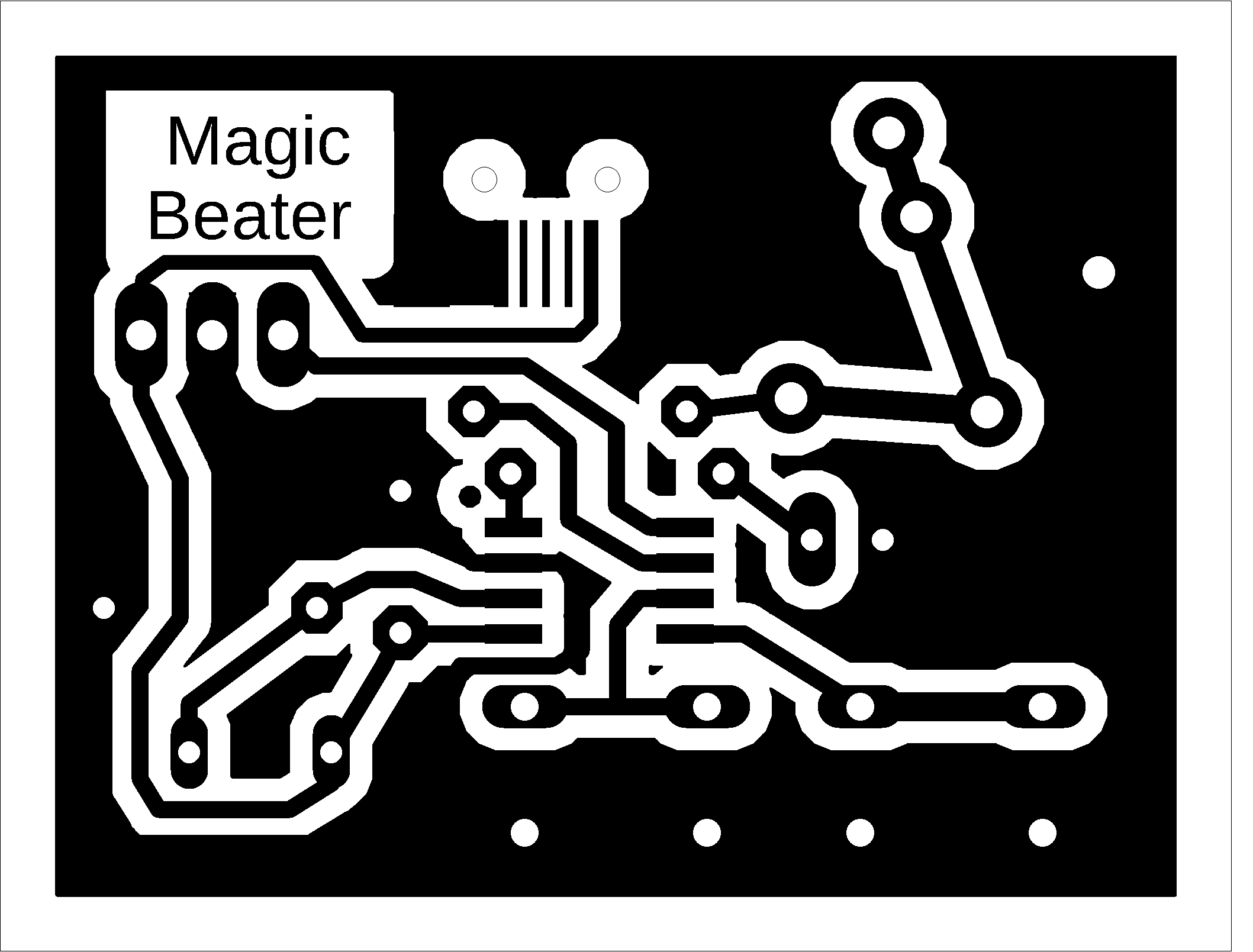
Magic Beater is a simple sound synthesizer-sequencer controlled by photosensor, with processor CH32V002J4M6. It allows you to play rhythms and melodies that repeat in a loop. The entire loop is 4 bars long - corresponding to 4 flashes of the indicator LED. Magic Beater is controlled by 2 buttons. Button A is used to record the melody. The pitch is determined by the light falling on the photodiode. The pitch can be controlled by modulating the light. If the tone range is not suitable (too high or too low), use a different R2 value, depending on the type of photodiode used. Button B is used to record the rhythm. Pressing buttons A and B simultaneously resets the memory.
Magic Beater is based on the RaveBOX v1.0 project, created by Vladimir Bartos https://github.com/Mat0ny/RaveBOX.
>>> The source codes and all necessary Magic Beater documentation can be found in the CH32LibSDK library in the ch32\TOYS\MagicBeater folder. https://github.com/Panda381/CH32LibSDK/tree/main/ch32/TOYS/MagicBeater <<<
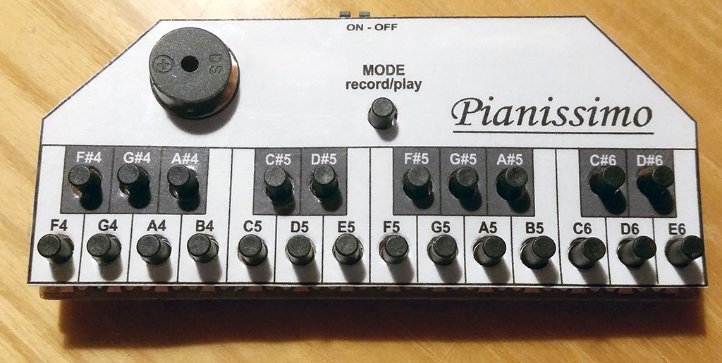
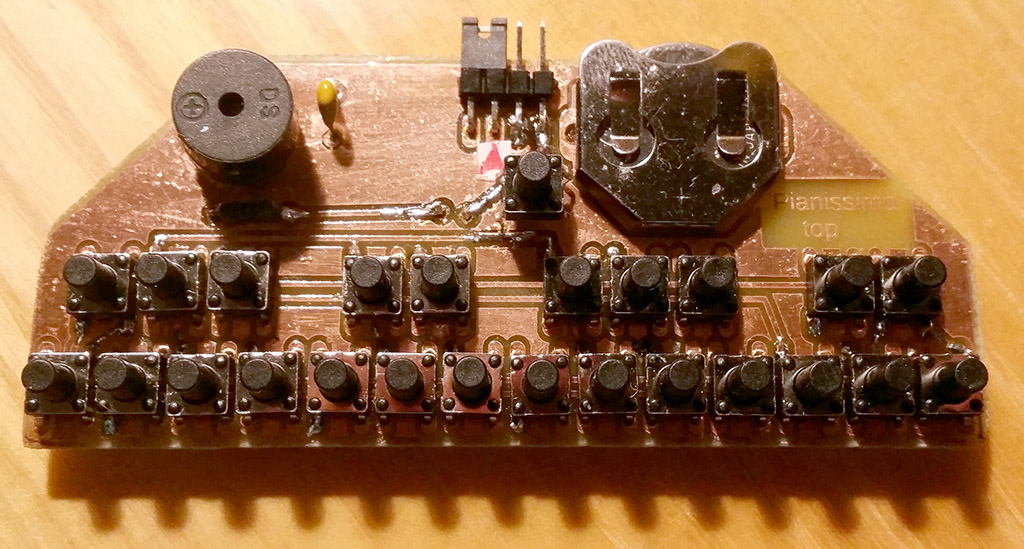
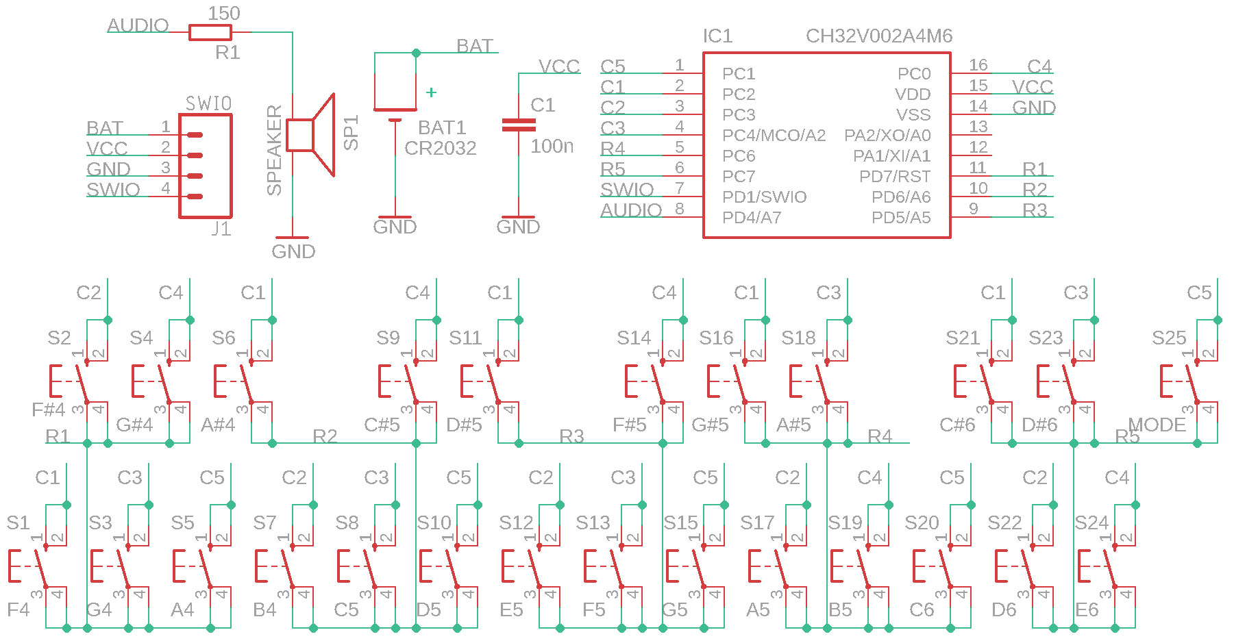
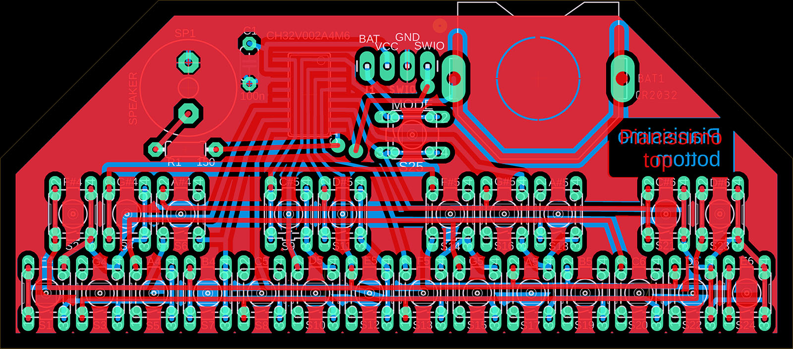
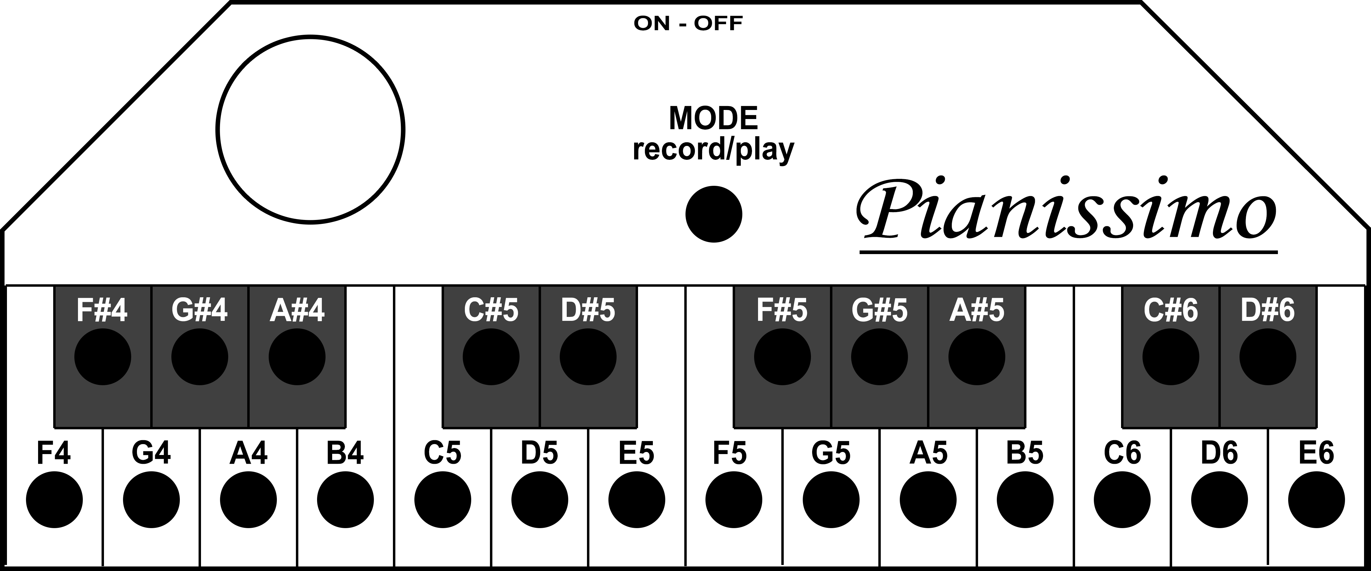
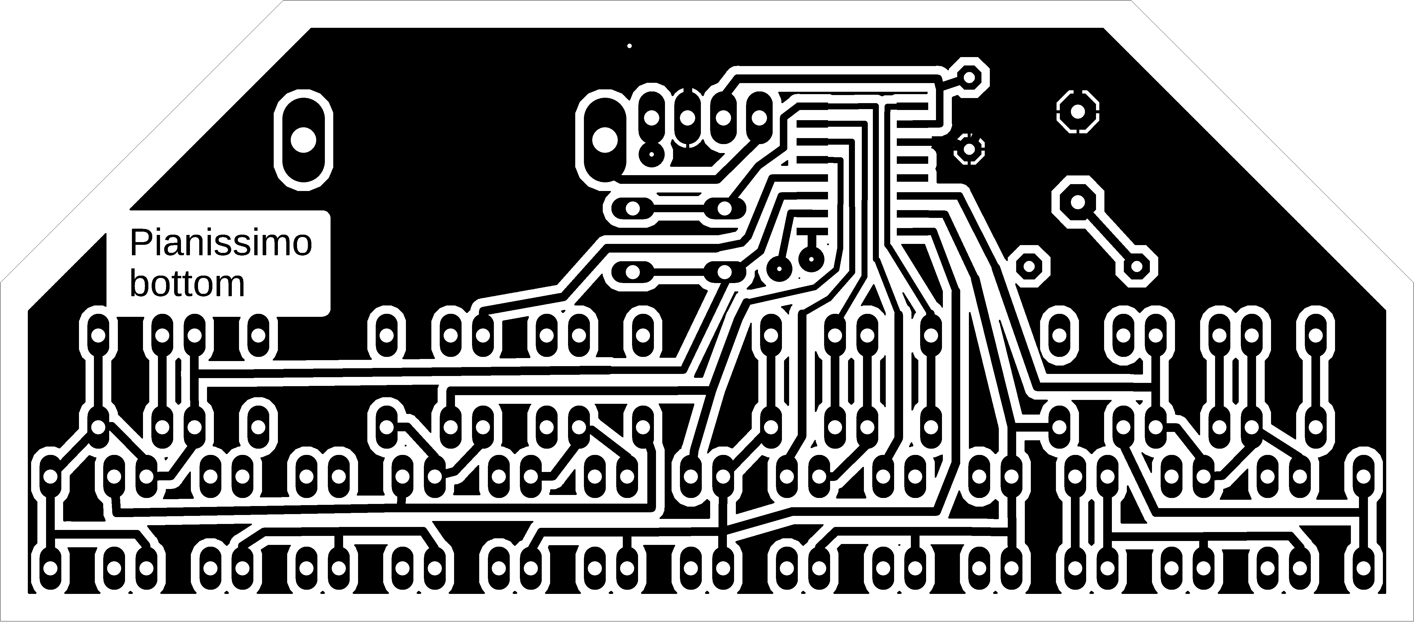
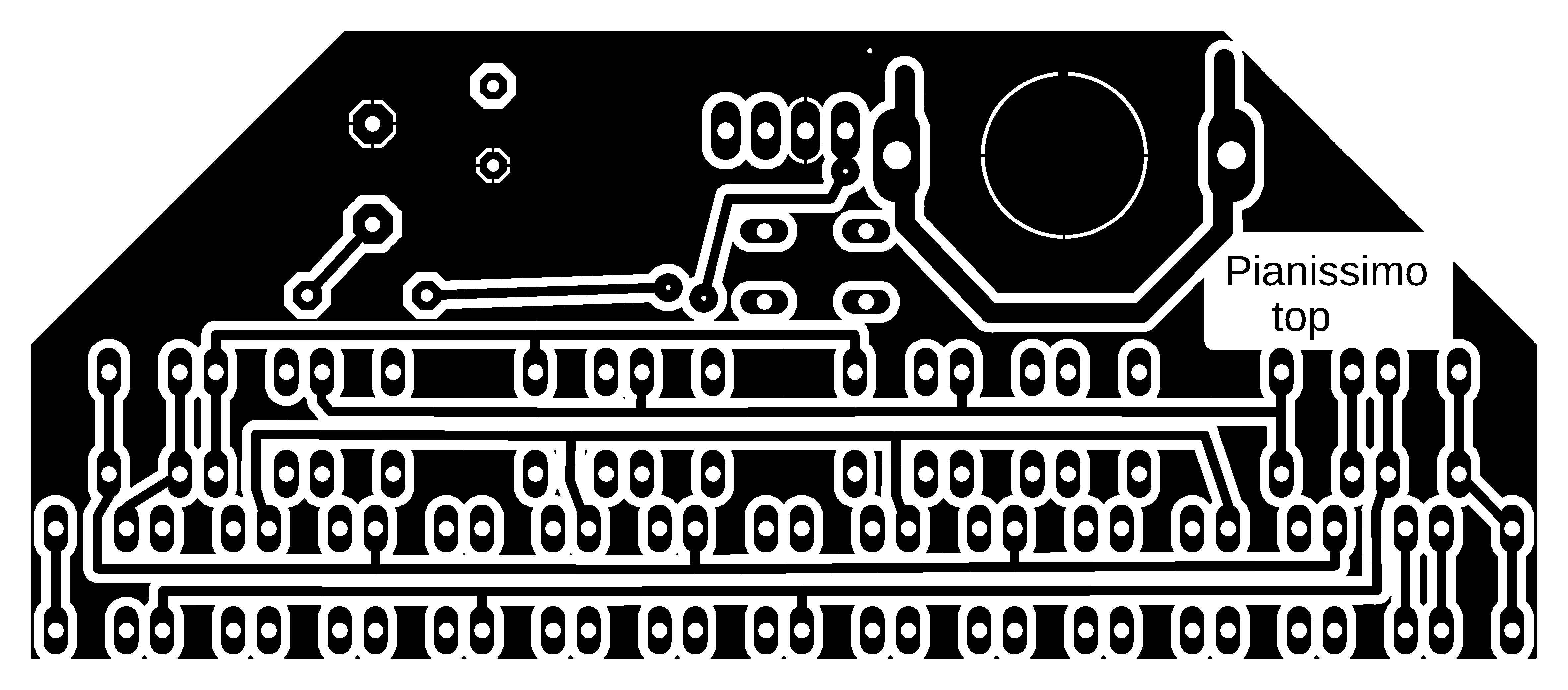
Pianissimo is a small electronic piano with a range of 2 octaves, a CH32V002A4M6 processor, and CR2032 battery power. In addition to basic tones, it also includes semitones. Using the MODE button, you can record a song up to 75 seconds long. During recording, the MODE button must be held down at all times. Recording starts when the first tone is pressed while holding down the MODE button. Pressing the MODE button again (without pressing any tone keys) will play back the recorded song. Playback can be interrupted by pressing any key, including the MODE button.
The tones are generated with the correct mutual accuracy of the tones. The time base is generated by an internal HSI oscillator, which is why the absolute tuning may deviate by up to 5%. If you connect a 24 MHz crystal to pins 12 and 13, together with 22pF capacitors, you will achieve accurate absolute tuning of the tones. It is not necessary to change the firmware, but after connecting the crystal, it is necessary to reset the processor by disconnecting the power supply.
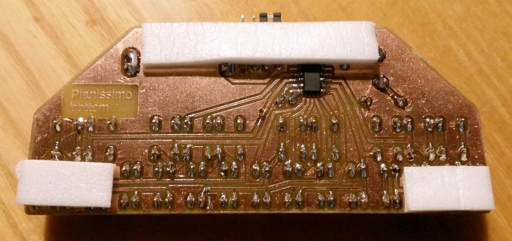
The piano is powered by a CR2032 battery. It can also be powered by an external voltage in the range of 3 to 5V. The programming connector is also used as a power switch - the device is turned on by connecting a jumper between the BAT and VCC pins. However, it is not necessary to use the power switch. If you do not need to program the processor, you can desolder the connector and simply connect the BAT and VCC pins. If the piano is not used for more than 5 seconds, the processor goes into power-saving mode, consuming only 10 uA from the battery. In power-saving mode, the battery will last for about 1 year. If you need to reprogram the processor, it may not be possible while the processor is asleep - you must wake up the processor by pressing any key or disconnecting the power supply, and then start programming the processor within 5 seconds.
>>> The source codes and all necessary Pianissimo documentation can be found in the CH32LibSDK library in the ch32\TOYS\Pianissimo folder. https://github.com/Panda381/CH32LibSDK/tree/main/ch32/TOYS/Pianissimo <<<
![]()
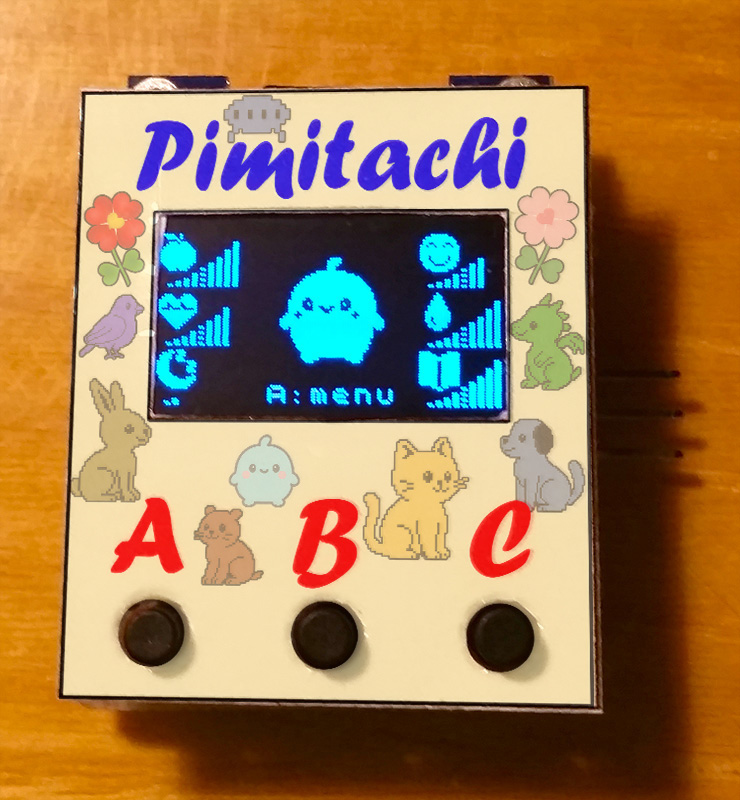
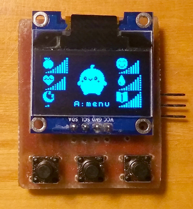
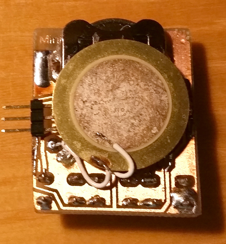
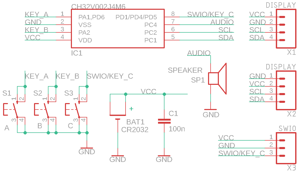
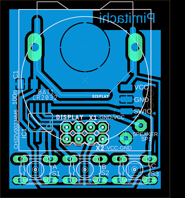
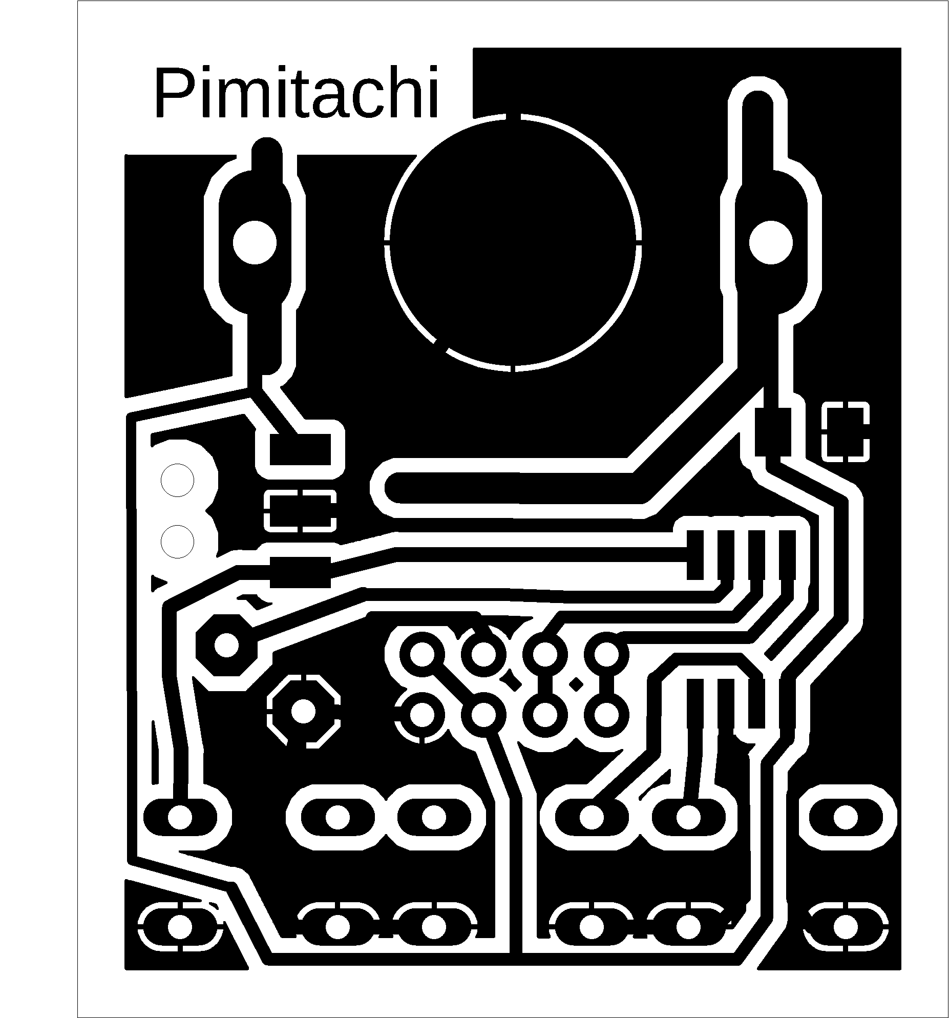
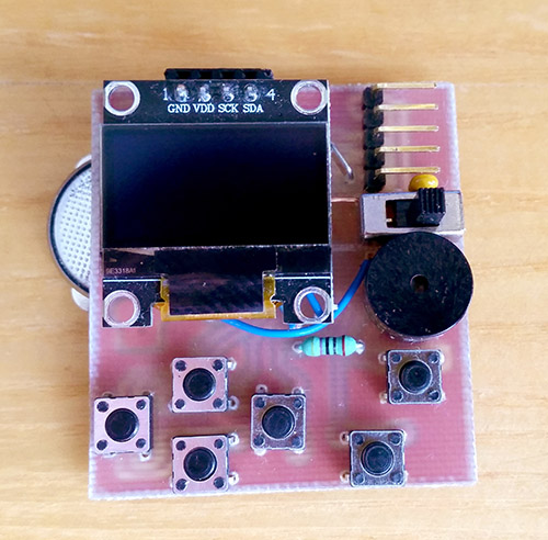
Pimitachi is a small pocket game in the style of Tamagotchi. In the game, you take care of a pet. The game includes an inexpensive 8-pin CH32V002J4M6 processor, 3 buttons, a 0.96" I2C OLED display SSD1306 128x64 pixels (e.g., this one https://www.hadex.cz/m508-displej-oled-096-128x64-znaku-iici2c-4piny-modry/ ), a piezo speaker, and a CR2032 battery. The design is very simple and suitable even for beginners.
Pay attention to the pin layout on the display - there are usually two versions, with the pin order VCC-GND-SCL-SDA or GND-VDD-SCL-SDA. The printed circuit board has positions prepared for both types of displays. The firmware can be uploaded to the processor using the WCH-LinkE programmer (available, for example, here: https://pajenicko.cz/usb-programator-a-debug-adapter-wch-link). Before reprogramming a previously programmed processor, it is necessary to disconnect and reconnect the power supply for a moment so that the processor is not in standby mode. After uploading the firmware, the programming connector is no longer needed and can be removed. Instead of the connector, simply solder the 3 wires from the programmer.
Story: Pimitachi are the children of the inhabitants of the planet Pimitarya. The Pimitaryans like to leave the upbringing of their children to the inhabitants of other planets so that they receive a proper education. If you are selected as a suitable candidate for the role of nanny, they will bring you an egg of their offspring. A little Pimitachi will hatch from the egg. Take good care of it so that it is happy and healthy. After 4 days, the Pimitachi will transform, and the toddler will become a young Pimitaryan. When it reaches the age of 21 days, its parents will take it back. If you take poor care of your charge and it becomes sick or unhappy, its parents will take it back sooner.

At the beginning of the game, you can choose the type of pet. There are 6 options to choose from. After choosing the type, you can edit its name or leave the default name. The choice of type and name cannot be changed later. The home screen displays the pet's status - hunger, health, tiredness, happiness, cleanliness, and training. Press the 'A' key to access the menu where you can feed, cure, sleep, play with, clean, or teach your pet. Press the 'B' key on the main screen to turn the sound on or off. In the menu, you can view information about your pet - its name, age, and maximum age - i.e., the planned departure date. If you neglect your pet, its maximum age will be reduced and the parents will take it away sooner. In the information section, you can also view the status of your previous pets. The last item in the menu is the early return of the pet to its parents. You can then choose a new pet.
If the game is not used for 30 seconds, it switches to low-power mode (20uA) with the display turned off. Even in this state, the game time continues to run. The current game status is saved to flash memory - both at the end of each day and when the game switches to low-power mode. So don't worry if the battery runs out - just replace the battery and continue playing. The status will be preserved even without the battery, only the time will not run without the battery.
>>> The source codes and all necessary Pimitachi documentation can be found in the CH32LibSDK library in the ch32\TOYS\Pimitachi folder. https://github.com/Panda381/CH32LibSDK/tree/main/ch32/TOYS/Pimitachi <<<

![]()
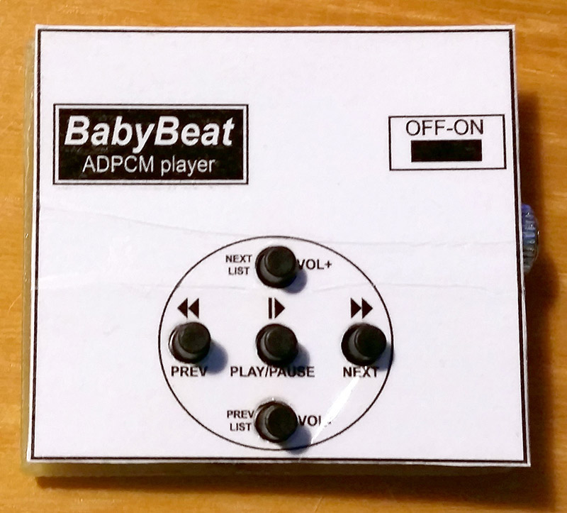
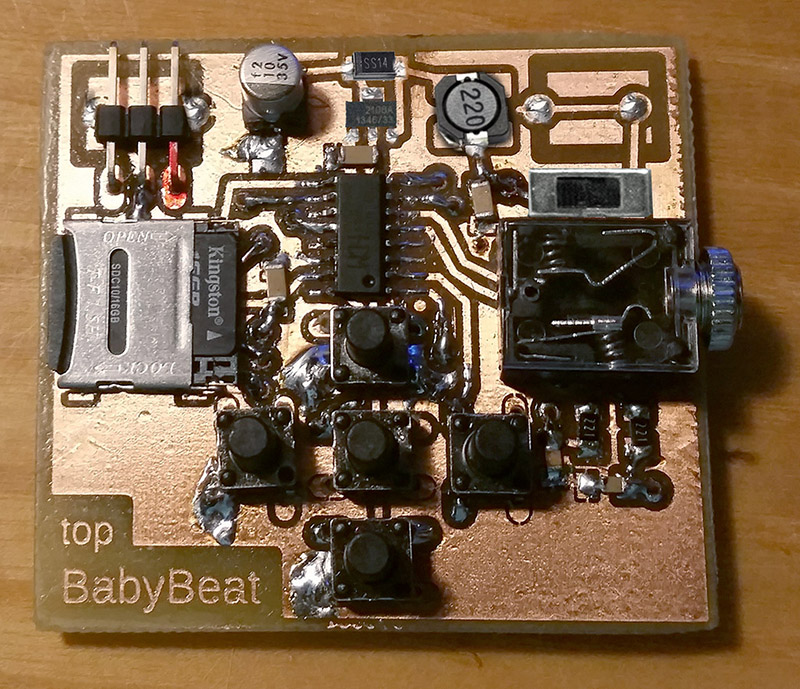
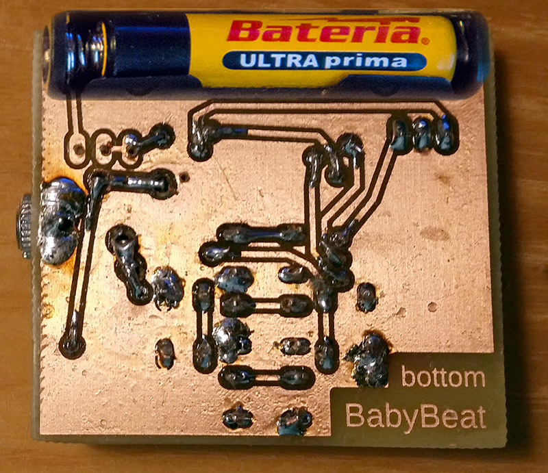
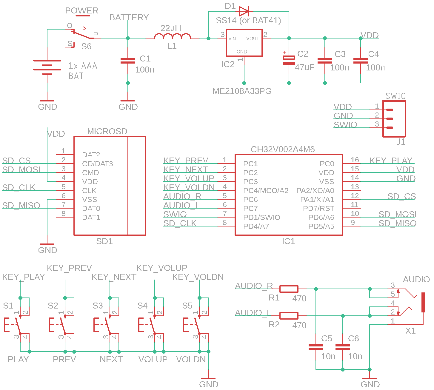
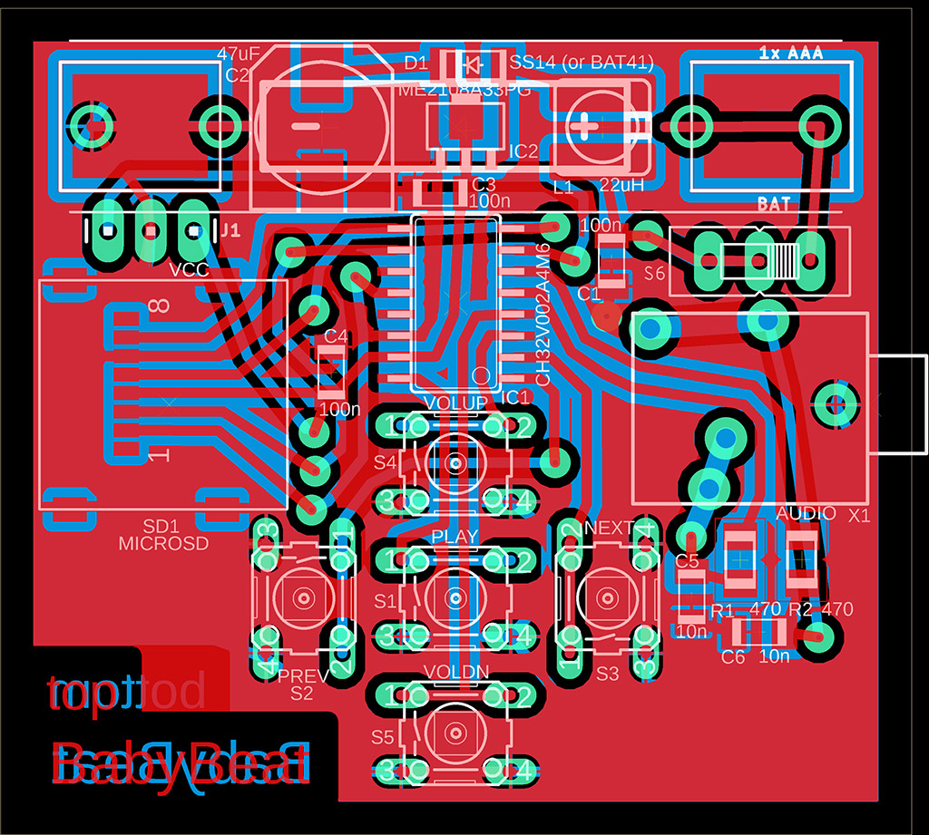
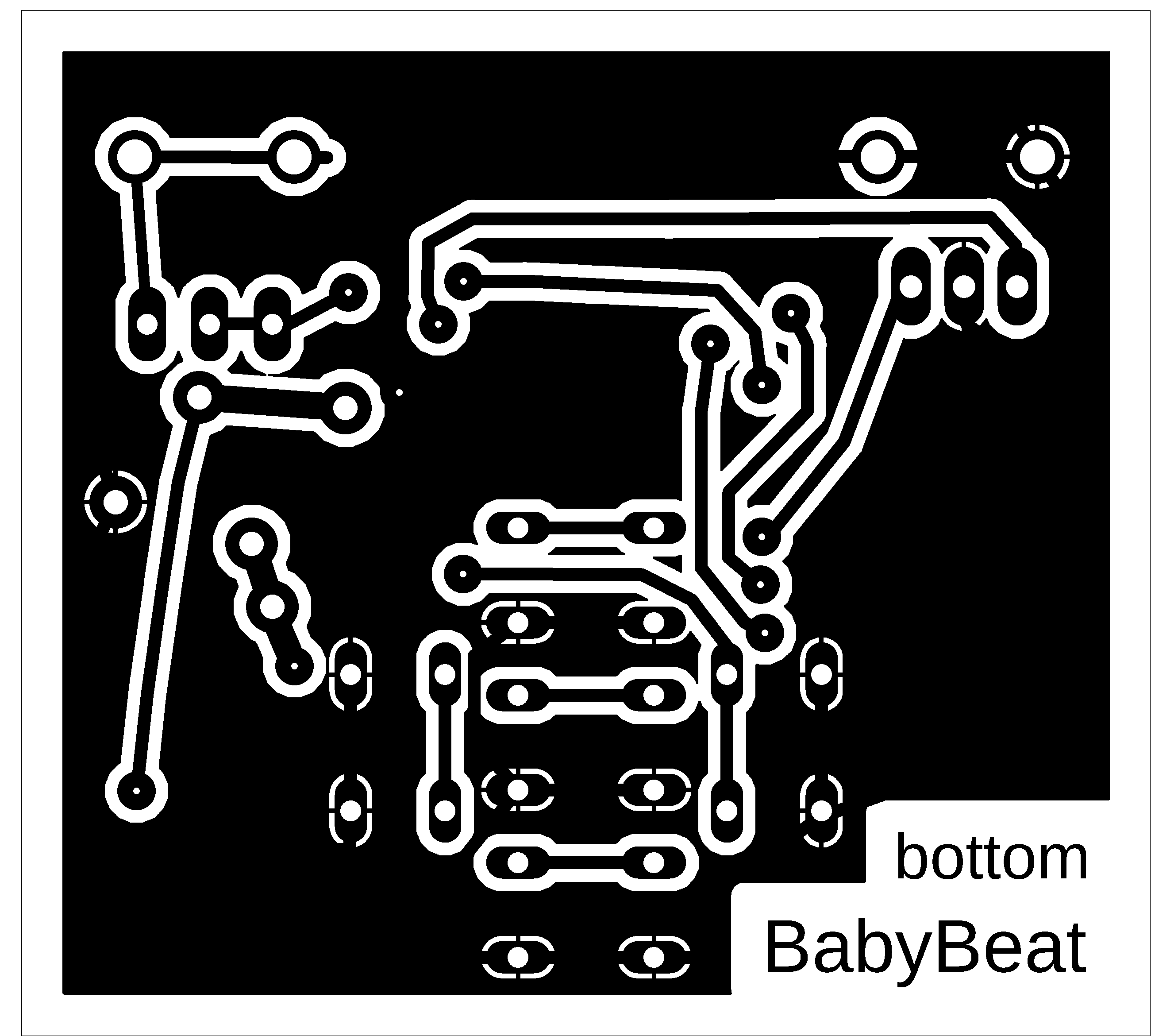
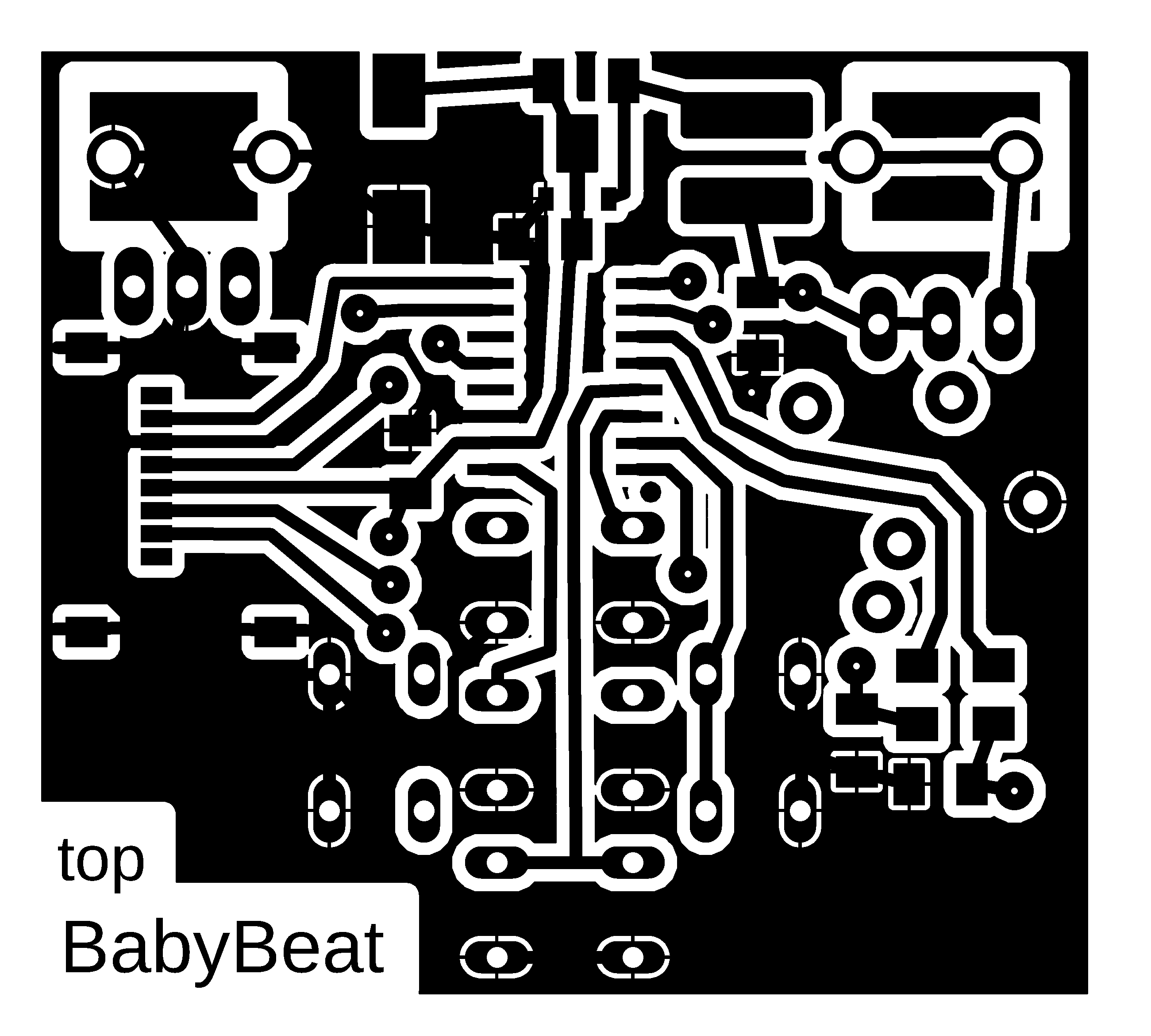
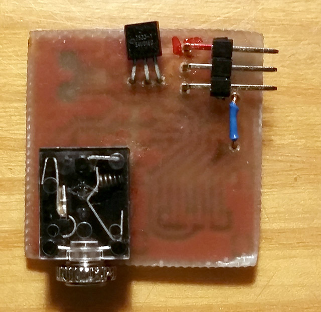
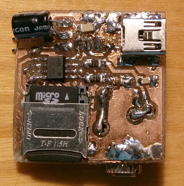
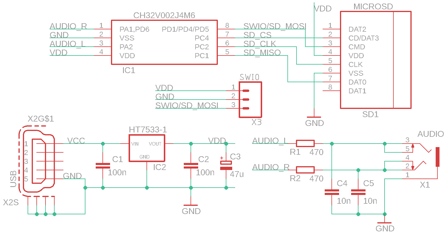
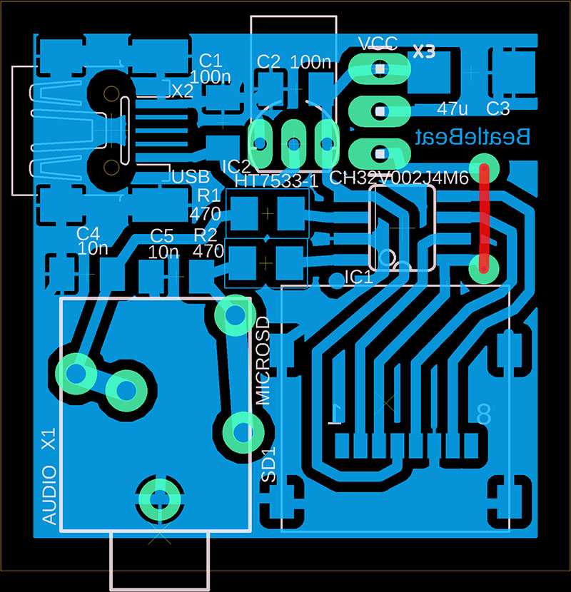
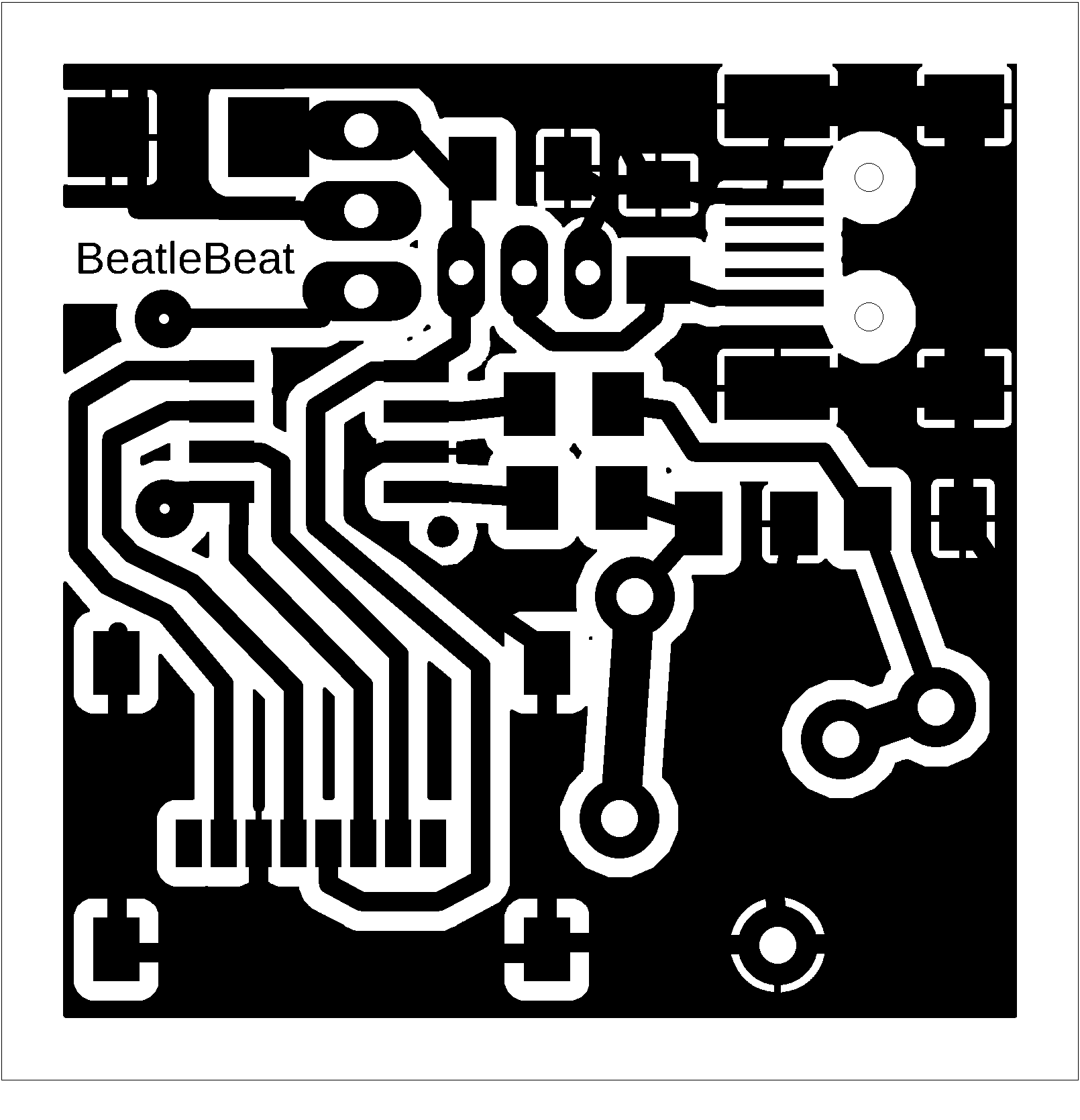
BabyBeat and BeatleBeat are stereo mini players for music files from SD card - "ImaPlayer". BabyBeat is a version with 5 buttons, a CH32V002A4M6 processor, powered by a 1.5V AAA battery and a 3.3V voltage converter. BeatleBeat is a minimalist version with a CH32V002J4M6 processor and USB power supply with a 3.3V stabilizer. The power supply for the players is only an example; everyone can certainly adjust the power supply to their liking. Please note that although the processor can be operated at 5V, the SD card requires a voltage of 3.3V. If you notice interference (humming) with some SD cards, it can be reduced by increasing the capacitor capacity in the power supply. The default volume can be adjusted by changing resistors R1 and R2.
The players only support WAV files in the IMA ADPCM 4-bit compression format, stereo, sample rate 22050 Hz (files should not contain metadata; example here). The correct file format is not checked, but will result in faulty sound (noise and hum). I recommend using FFmpeg to convert files. For batch conversion, you can use the following BAT file, which will convert all MP3 tracks from the IN folder and save them to the OUT folder:
@echo off
del OUT\*.wav
for %%f in (IN\*.mp3) do ffmpeg -i "%%f" -y -c:a adpcm_ima_wav -ar 22050 -ac 2 -map_metadata -1 "OUT\%%~nf.wav"
Save the files to an SD card formatted to FAT32. The first album is stored in the root folder of the SD card. Additional albums are stored in subfolders. Albums in subfolders can only be used with the BabyBeat player. BeatleBeat only plays songs from the root folder. The order in which songs and albums are played is determined by the order in which they are saved on the SD card (songs are not sorted). For proper sorting, I recommend deleting old files on the SD card, removing the card, and reinserting it into the reader after a while, and only then copying the files to the card.
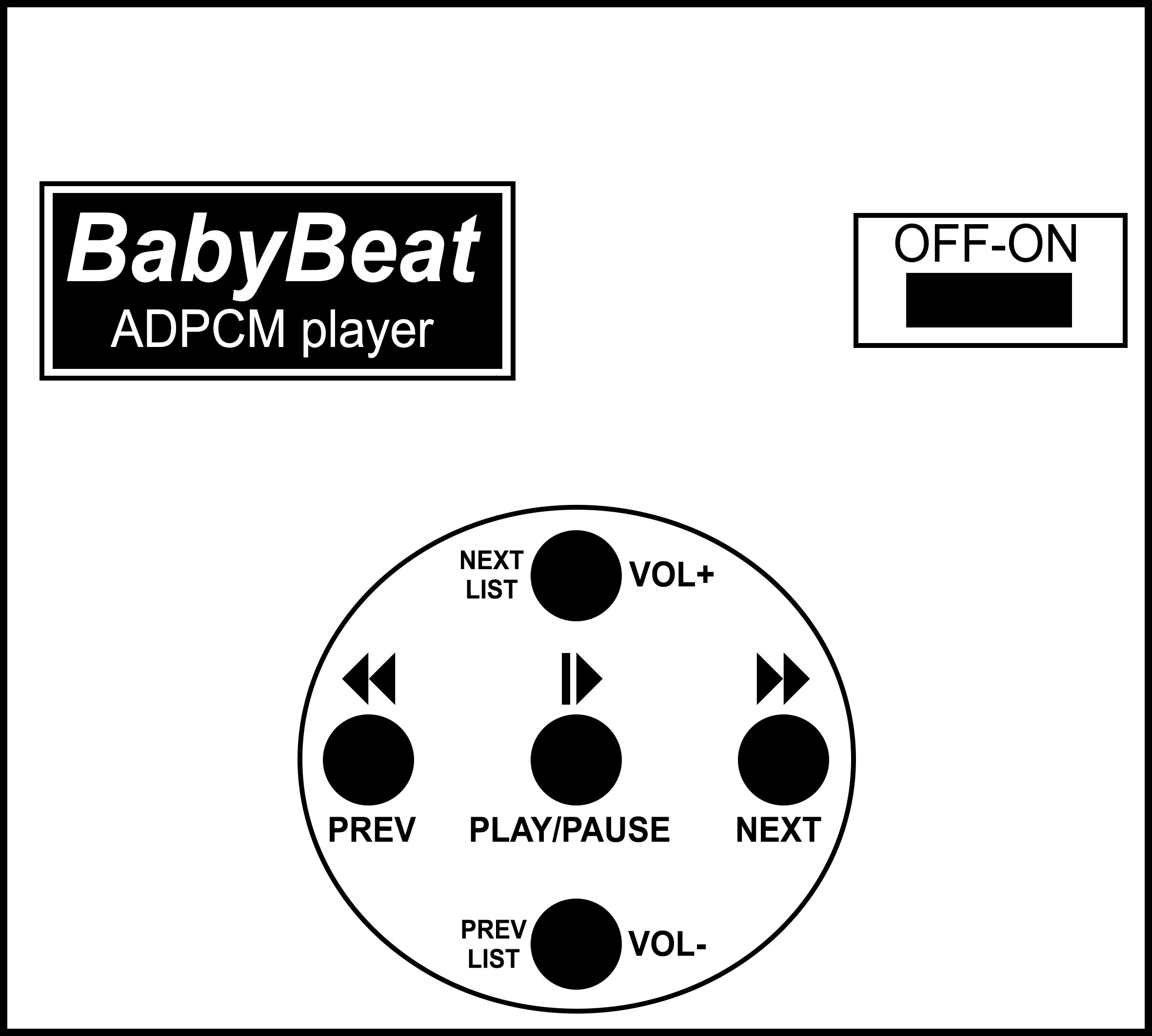
BabyBeat control buttons:
PLAY/PAUSE ... Pause/resume playback.
NEXT ... A short press skips to the next track in the current album. From the last track, it skips back to the first track of the album. Press and hold (longer than 0.5 seconds) to move the playback forward by 10 seconds. Hold further to skip further after 1 second.
PREV ... Press shortly to move playback to the previous track in the current album. From the first track, it will skip to the last track in the album. A long press (longer than 0.5 seconds) moves the playback back 10 seconds. Hold further to skip further after 1 second.
VOL+, NEXT LIST - A short press increases the volume. A long press (longer than 0.5 seconds) skips to the next album (to next folder).
VOL-, PREV LIST - A short press decreases the volume. A long press (longer than 0.5 seconds) skips to the previous album (to previous folder).
BeatleBeat has no control buttons. It plays all songs in the root folder of the SD disk sequentially.
>>> The source codes and all necessary BabyBeat/BeatleBeat documentation can be found in the CH32LibSDK library in the ch32\DEVICE folder. https://github.com/Panda381/CH32LibSDK/tree/main/ch32/DEVICE <<<
BabyBeat:
BeatleBeat:
![]()
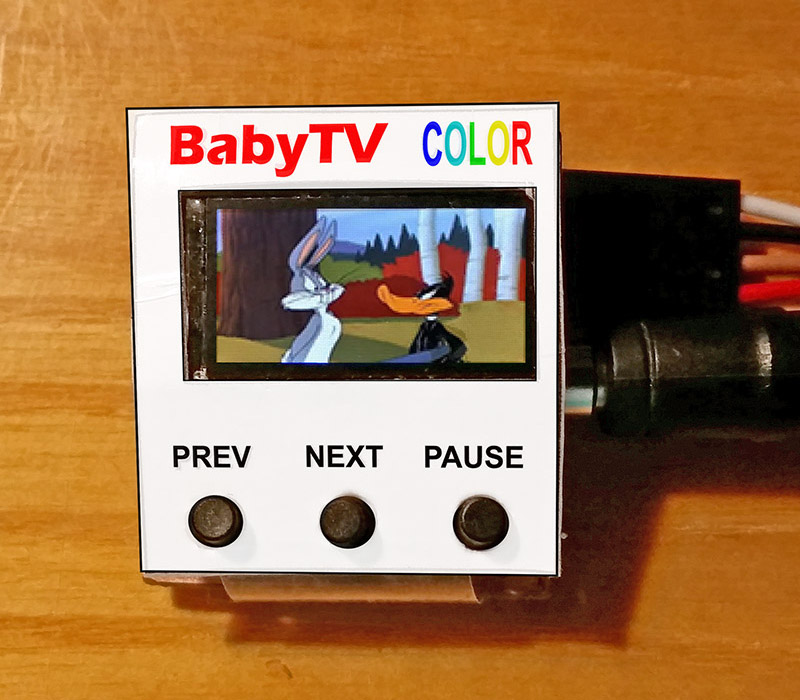
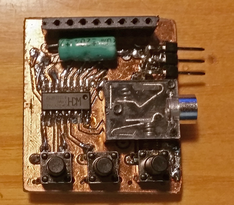
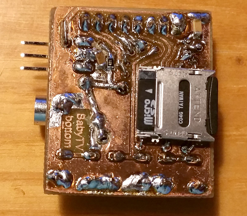
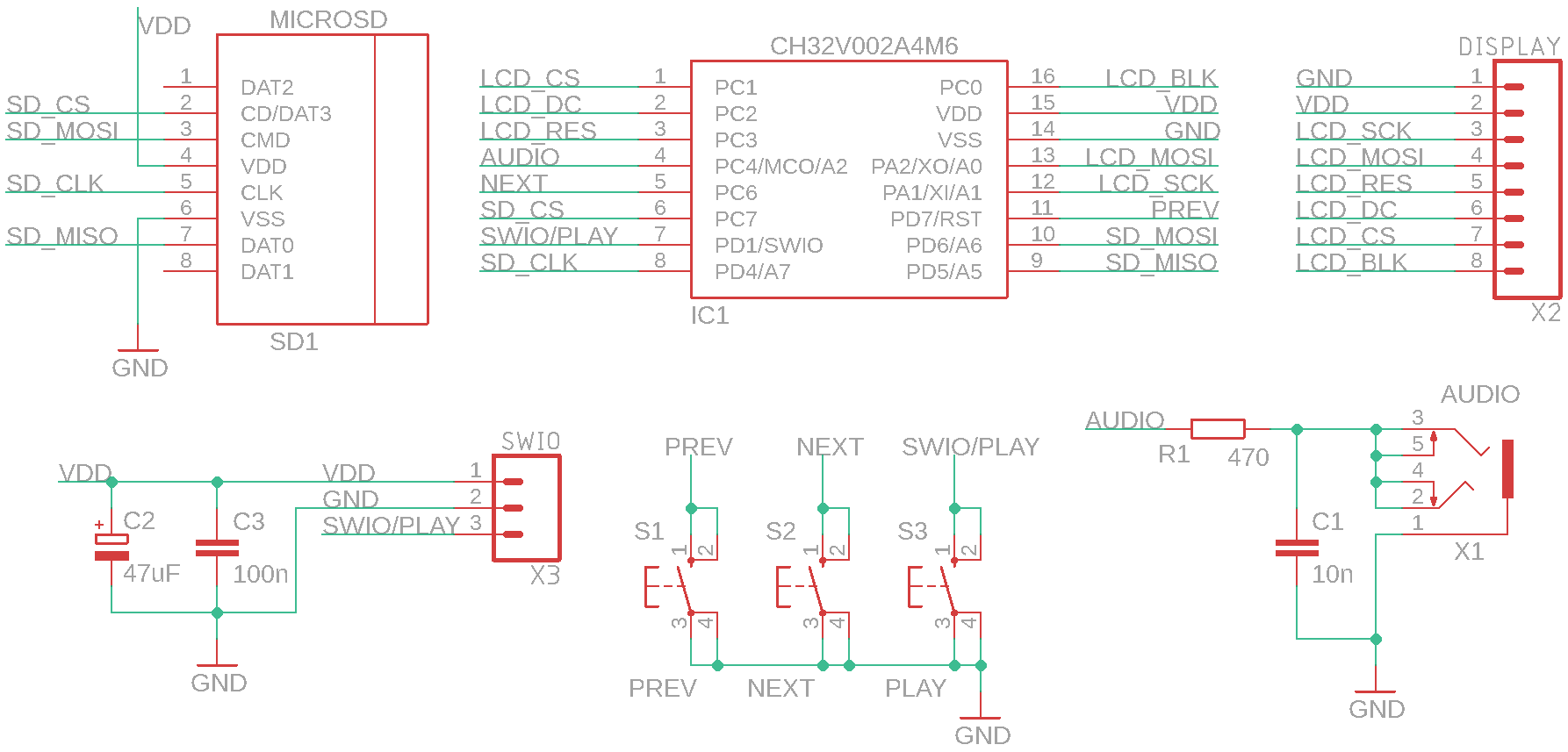
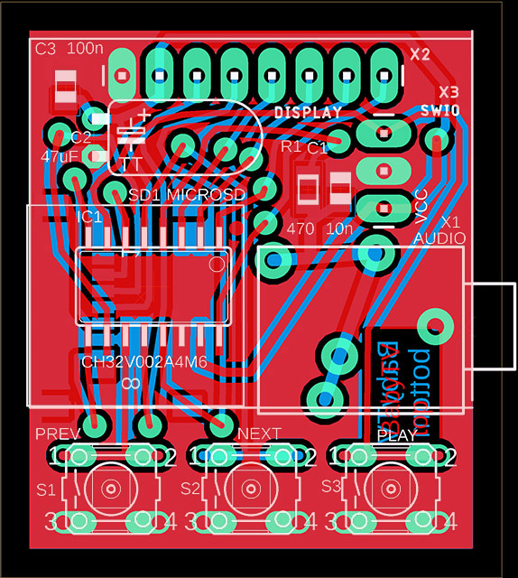
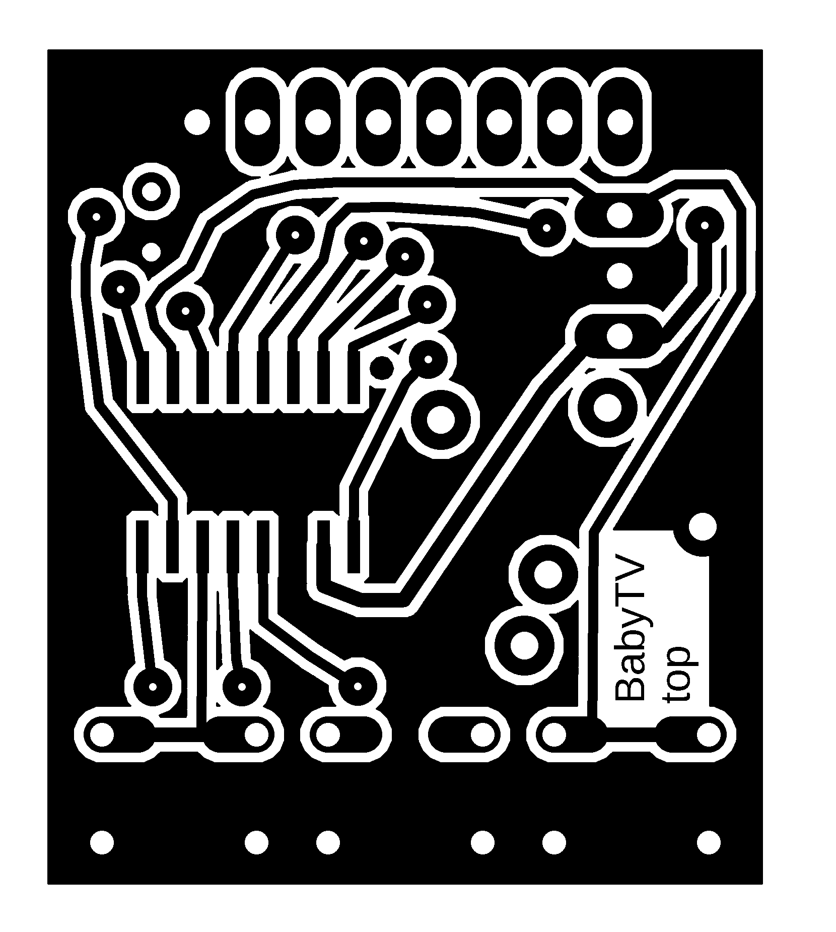
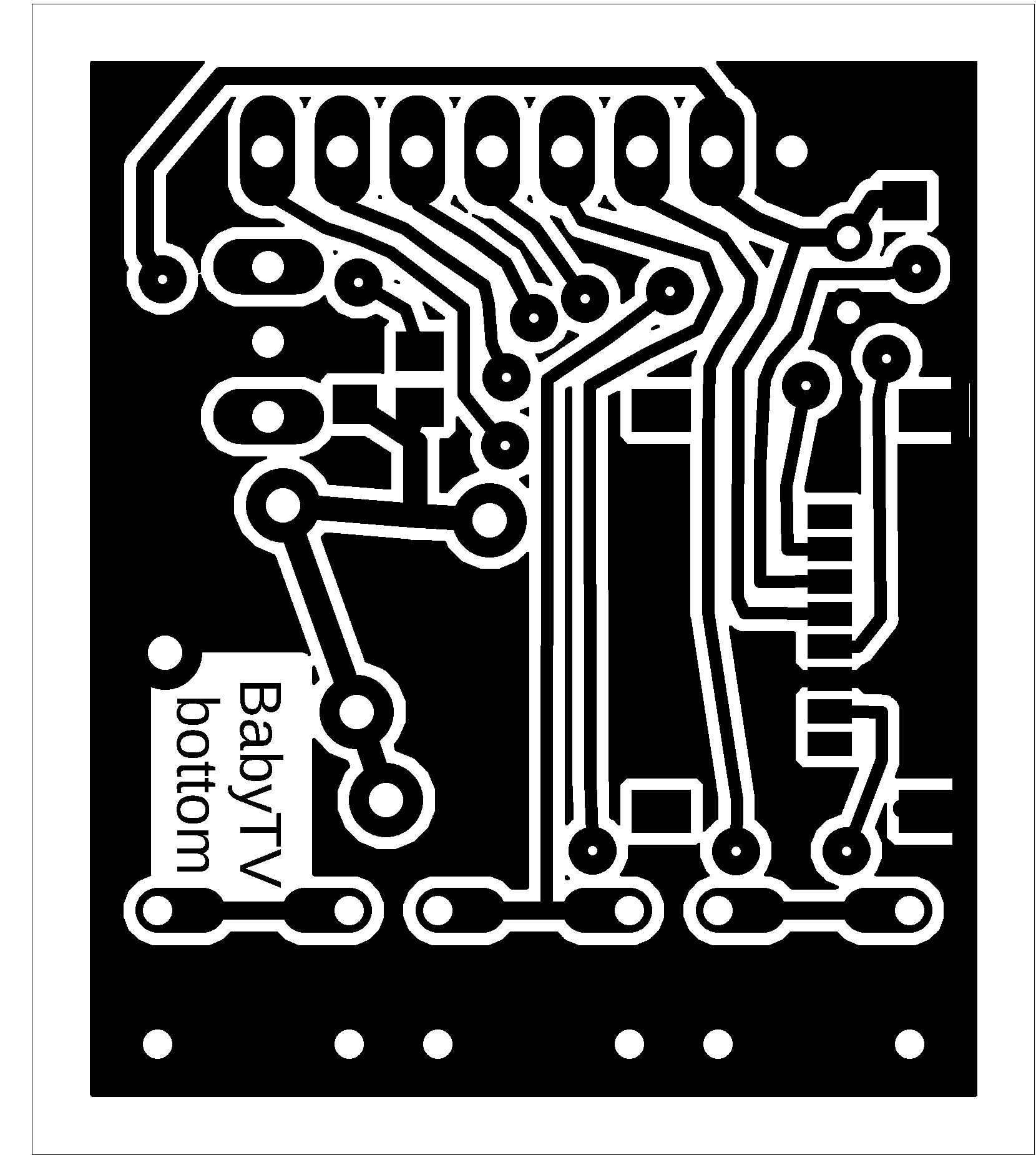
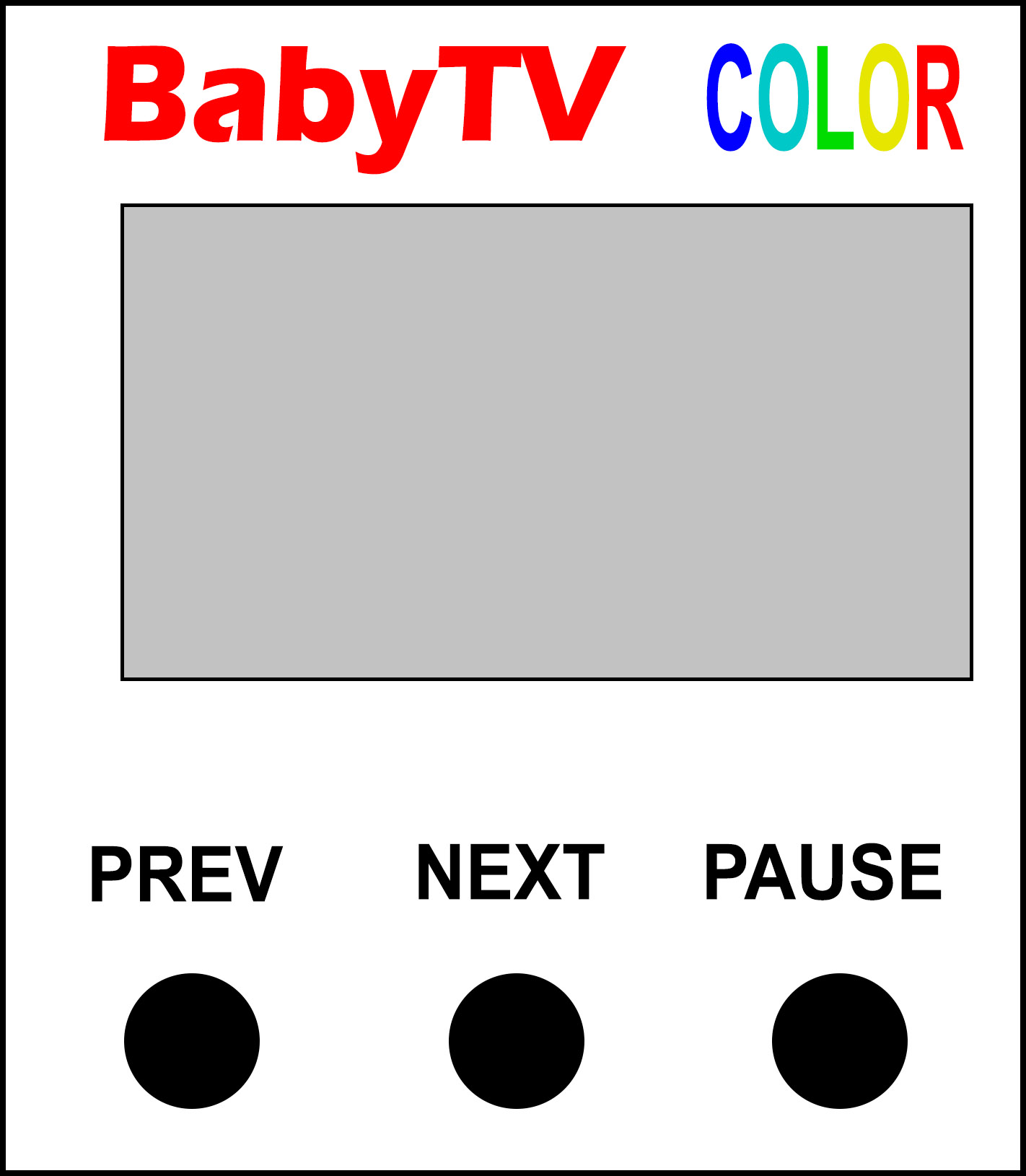
BabyTV is a miniature video player from an SD card, with a CH32V002A4M6 processor and a 160x80 pixel SPI LCD color display. The display is a 0.96" ST7735S SPI IPS LCD with a resolution of 160x80 pixels, ST7735S controller, and 3.3V voltage (https://pajenicko.cz/komponenty/displeje/barevny-displej-ips-0.96-80x160-st7735s-spi ). In addition to the display, the player only has 3 control buttons, a microSD card slot, an audio connector, 1 resistor, and 2 capacitors. The prototype does not handle power supply - the player is powered from an external 3.3V source (programmer). The power source can be, for example, a 1.5V single cell battery with a ME2108 3.3V voltage converter (https://pajenicko.cz/miniaturni-menic-napeti-step-up-me2108-0.9v-3.3v-na-3.3v-az-400ma ) or a 3.7V battery with a 3.3V linear stabilizer.
The player requires a special file format - with the extension *.BTV. In the ch32\DEVICE\BabyTV folder, there is a command file called !conv_all.bat, which converts all *.AVI and *.MP4 files in the folder to the target format *.BTV. The FFmpeg program is required for conversion. Download the "ffmpeg-*.7z" file from https://www.ffmpeg.org/download.html and extract the "bin\ffmpeg.exe" program from it into a folder. The ImageMagick program is also required. Download the "ImageMagick-*-portable-Q16-x64.7z" file from https://imagemagick.org/script/download.php and extract the "magick.exe" program to a folder. And thirdly, you need the BTVenc\BTVenc.exe program, which is already in the folder.
During conversion, a temporary folder called "temp" will be created. Using FFmpeg, images in PNG format with FPS=4 and dimensions of 160x80 pixels will be exported from the video into this folder. Next, FFmpeg is used to export the audio track in PCM 16000Hz mono format to the folder. ImageMagick is used to convert all *.PNG images to *.BMP 8-bit format with palettes and dithering. Finally, all files are combined into a target file using the BTVenc.exe program. During conversion, the audio track is compressed using the IMA ADPCM 4-bit method. Images are compressed using A6 attribute compression (see the DispHSTX driver in PicoLibSDK).
After conversion, save all *.BTV videos to the root folder of a FAT32 microSD card. Video playback runs at 4 FPS. It is recommended to adjust the audio track to maximum volume in advance. If the audio track is too quiet, you may hear a humming noise from the power supply in the sound. If the humming is noticeable even at sufficient volume, it may help to increase the capacity of the filter capacitor in the power supply, or possibly the PWM signal output (32kHz) via a switched gate with filtered power supply, and only then filtering with an RC element. Meaning of control buttons:
PREV ... A short press moves playback to the previous video. A long press (and hold) moves playback back 30 seconds.
NEXT ... A short press moves playback to the next video. A long press (and hold) moves playback forward 30 seconds.
PAUSE ... Pauses/resumes video playback.
You can find several sample videos in the library in the ch32\DEVICE\BabyTV\samples folder. If you need to reprogram the processor repeatedly, disconnect it from the power supply, reconnect it, and start programming within 3 seconds, otherwise the programming pin will disconnect after that time. Alternatively, remove the SD card; the processor will remain in programmable mode after powering up.
>>> The source codes and all necessary BabyTV documentation can be found in the CH32LibSDK library in the ch32\DEVICE\BabyTV folder. https://github.com/Panda381/CH32LibSDK/tree/main/ch32/DEVICE/BabyTV <<<

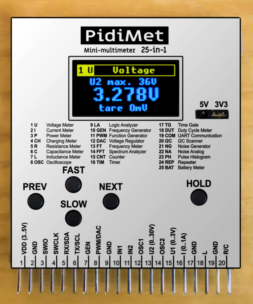
PidiMet is small, low-cost, universal multimeter with 25 functions and CH32V006 processor. It includes measure of voltage, current, power, charging, resistance, capacitance, inductance, oscilloscope, logic analyzer, frequency generator, function generator, voltage regulator, frequency meter, spectrum analyzer, counter, timer, time gate, duty cycle, UART communication, I2C scanner, noise generator, analog noise, pulse histogram, repeater, and battery meter.
Details about the project can be found on a separate website https://www.breatharian.eu/hw/pidimet/index_en.html and on GitHub https://github.com/Panda381/PidiMet .
>>> The source codes and all necessary PidiMet documentation can be found in the CH32LibSDK library in the ch32\DEVICE\PidiMet folder. https://github.com/Panda381/CH32LibSDK/tree/main/ch32/DEVICE/PidiMet <<<
TinyBoy is an adaptation of CH32V003-Game Console by Stefan Wagner, prepared by Tomas Vecera for the CH32LibSDK library and the CH32V002J4M6 processor. TinyBoy is not yet part of the CH32LibSDK library. Link to the project: https://github.com/tvecera/CH32LibSDK/tree/main/_devices/tinyboy .
Download library along with sample applications and all resources
In the "_devices\<console>\diagram\" folders, you will find console schematic diagrams.
In the "!<console>" folders, you will find compiled sample programs.
The "<console>" folders contain the source codes for sample console applications.
Miroslav Nemecek