Cesky: |
BarePi
Modular Microchip Kit
Last Update: 07/18/2026
(c) 2026 Miroslav Nemecek
https://github.com/Panda381/BarePi
Download sources of the BarePi kit (100 MB)
Note: The schematics and PCBs are in KiCAD version 9 format. The PCBs were originally designed for home production using photolithography and may not be properly prepared for professional production. If you want to have your PCBs professionally produced, I recommend checking the designs carefully, especially the dimensions of the components, which may not be correctly defined. Typically, SMD capacitors may not have the correct dimensions.
Note 2: A WCH-LinkE programmer (available e.g. here) may be required to program CH32xxx processors. Before using it for the first time, it may be necessary to upgrade the firmware of the programmer first - this can be done in the MounRiver Studio development environment.
Description of the kit (basic characteristics of the kit)
Bus connector (description of signals on the bus connector)
Display connector (description of signals on the display connector)
ZeroTiny (example of a minimalist game console with a Raspberry Zero module, created based on kit modules)
EEPROM and driver formats (structure of EEPROMs and Register-Controlled Drivers)
Special modules
Base (basic module - USB power supply, 3.3V stabilizer, audio output, microSD card, Reset button)
BusExp (bus expander for connecting 4 modules)
Port (ports SPI, I2C, UART, digital I/O, ADC)
RTC (real-time clock and EEPROM memory)
TestLed (bus tester)
Processors
MegaTinyJoypad (Mega Tiny Joypad game console, ESP-07S processor module, 128x64 OLED display)
PGA2350 (PicoPadPGA game console, RP2350 processor)
PicoPad (PicoPad console, RP2040 or RP2350 processor)
PicoPadHSTX (PicoPadHSTX console with VGA or HDMI output, RP2350 processor)
PidiBoy (PidiBoy console, CH32V006F8P6 processor, 128x64 OLED display)
PidiMet, PidiMetAdapter (universal multimeter)
PidiPad (PidiPad console, CH32V006E8R6 processor, output to VGA monitor)
SumoPad (SumoPad console, CH32V208RBT6 processor, output to VGA monitor or LCD display 320x240)
TinyJoypad (Tiny Joypad game console, ATtiny85 processor, 128x64 OLED display)
TweetyBoy (TweetyBoy game console, CH32X035G8R6 processor, 160x80 LCD display)
Zero (Raspberry Zero 1 or Raspberry Zero 2 module)
Displays
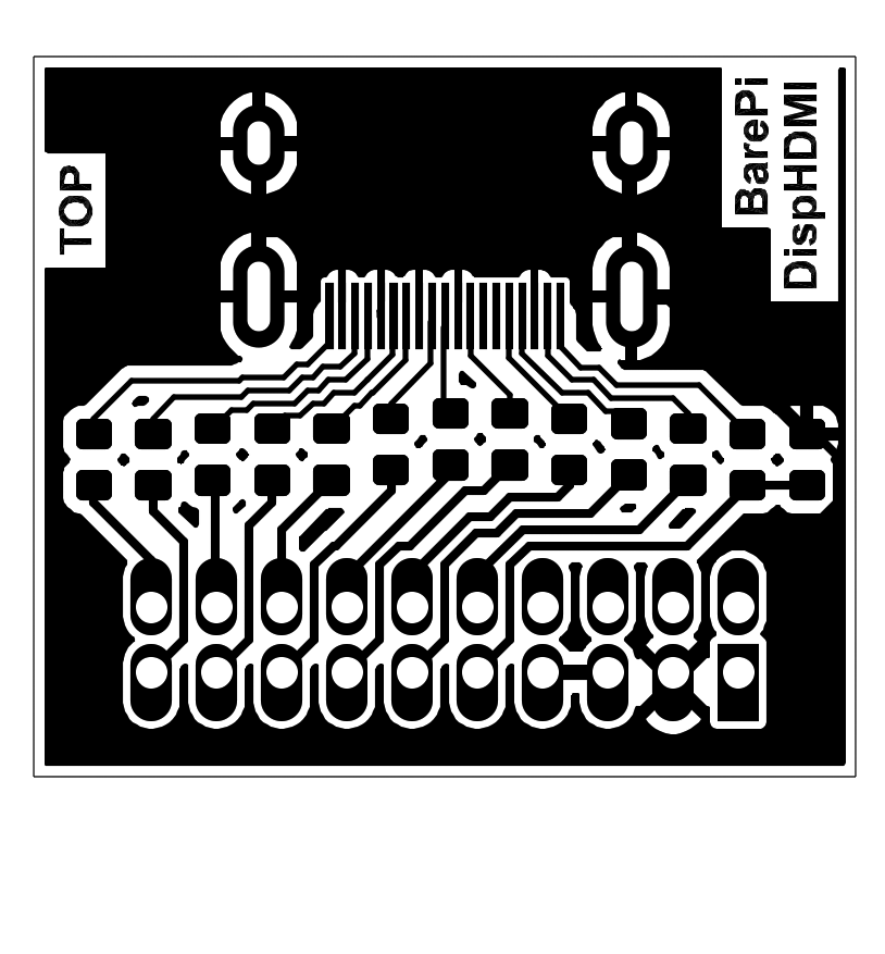
DispHDMI (adapter for connecting an HDMI monitor)
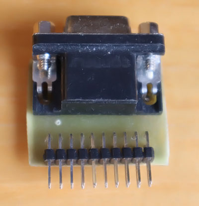
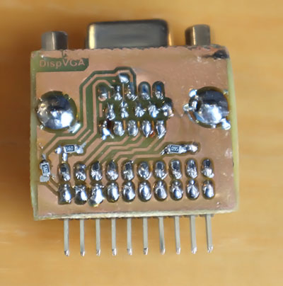
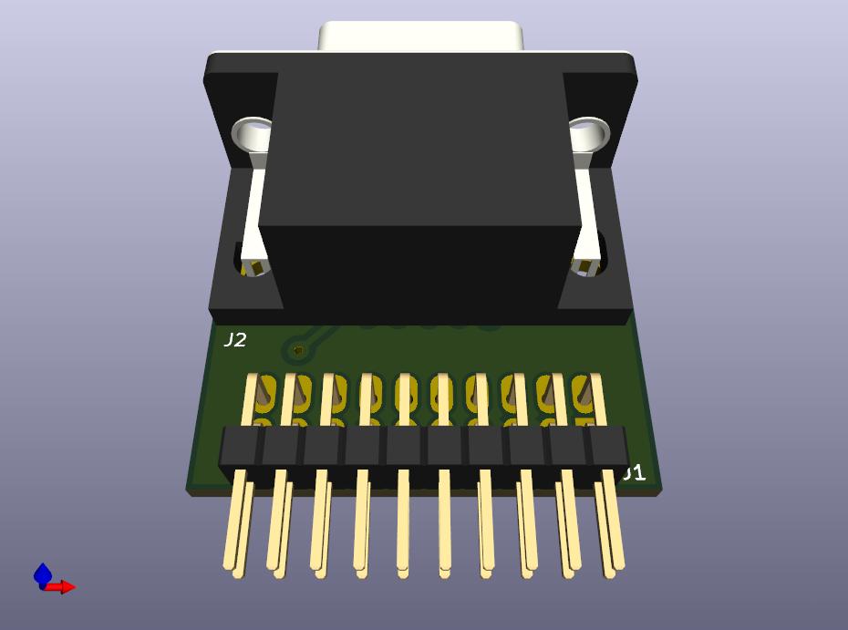
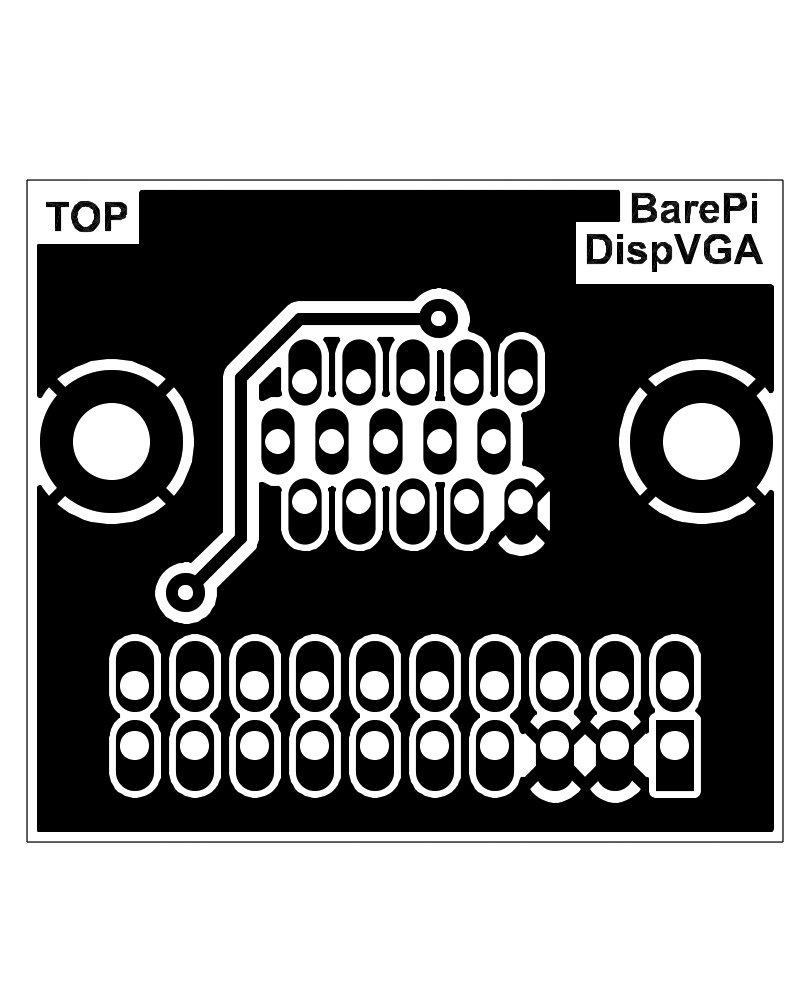
DispVGA (adapter for connecting a VGA monitor)
ExtDisp (converter for grabbing a 320x240 LCD display and displaying it on a VGA or HDMI monitor)
LCD16x2 (text LCD display, 2 rows of 16 characters)
LCD160x80 (LCD color display 160x80)
LCD320x240 (LCD color display 320x240)
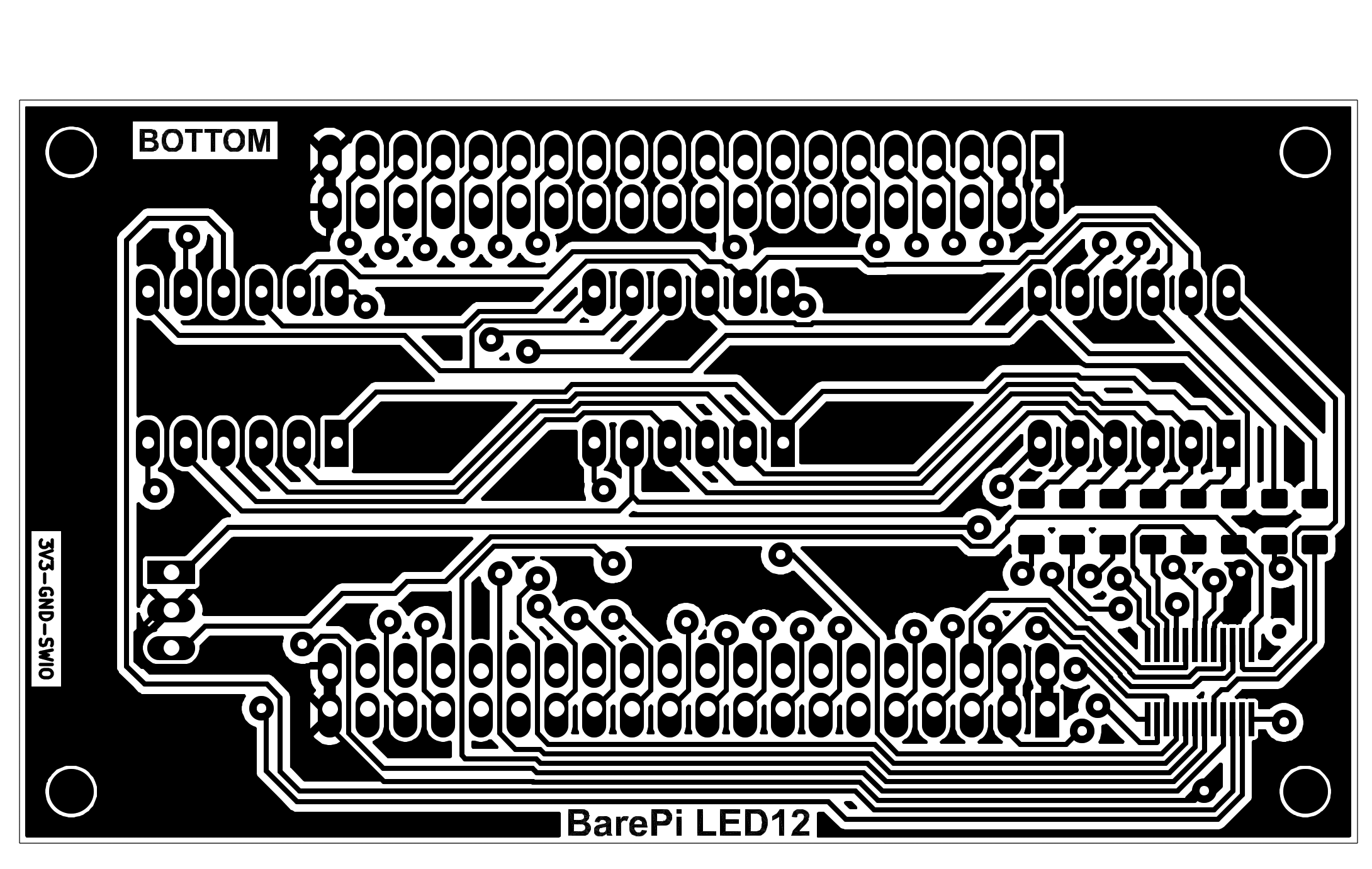
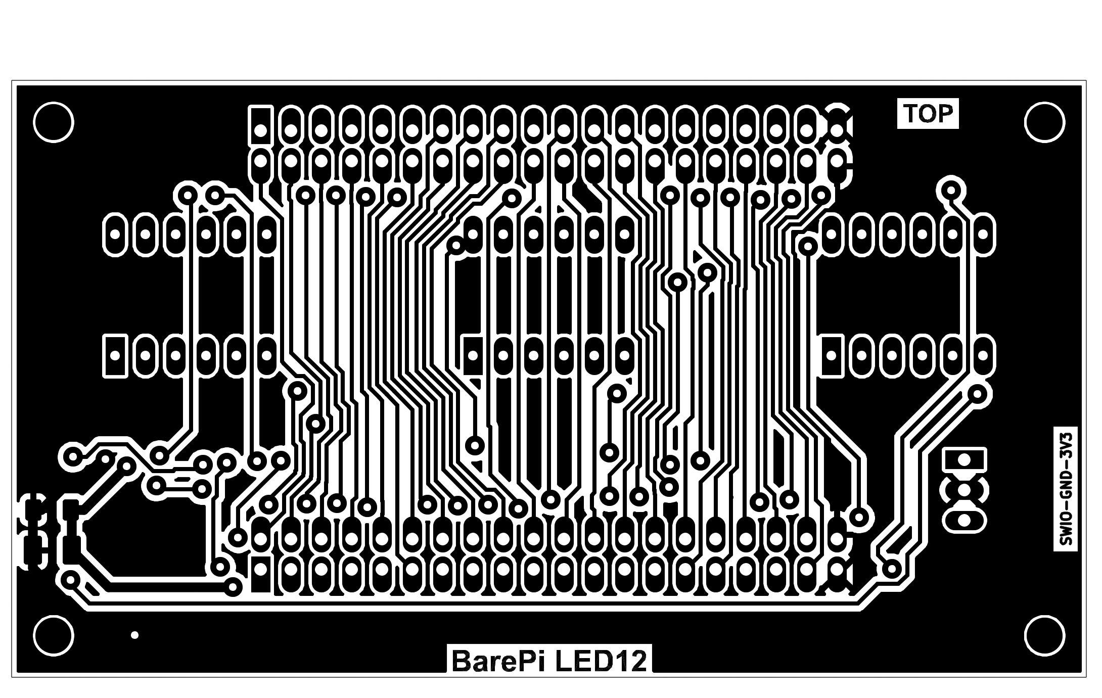
LED12 (7-segment LED display with 12 positions)
OLED128x64 (OLED black and white display 128x64)
Keyboard
CalcKey (calculator keyboard)
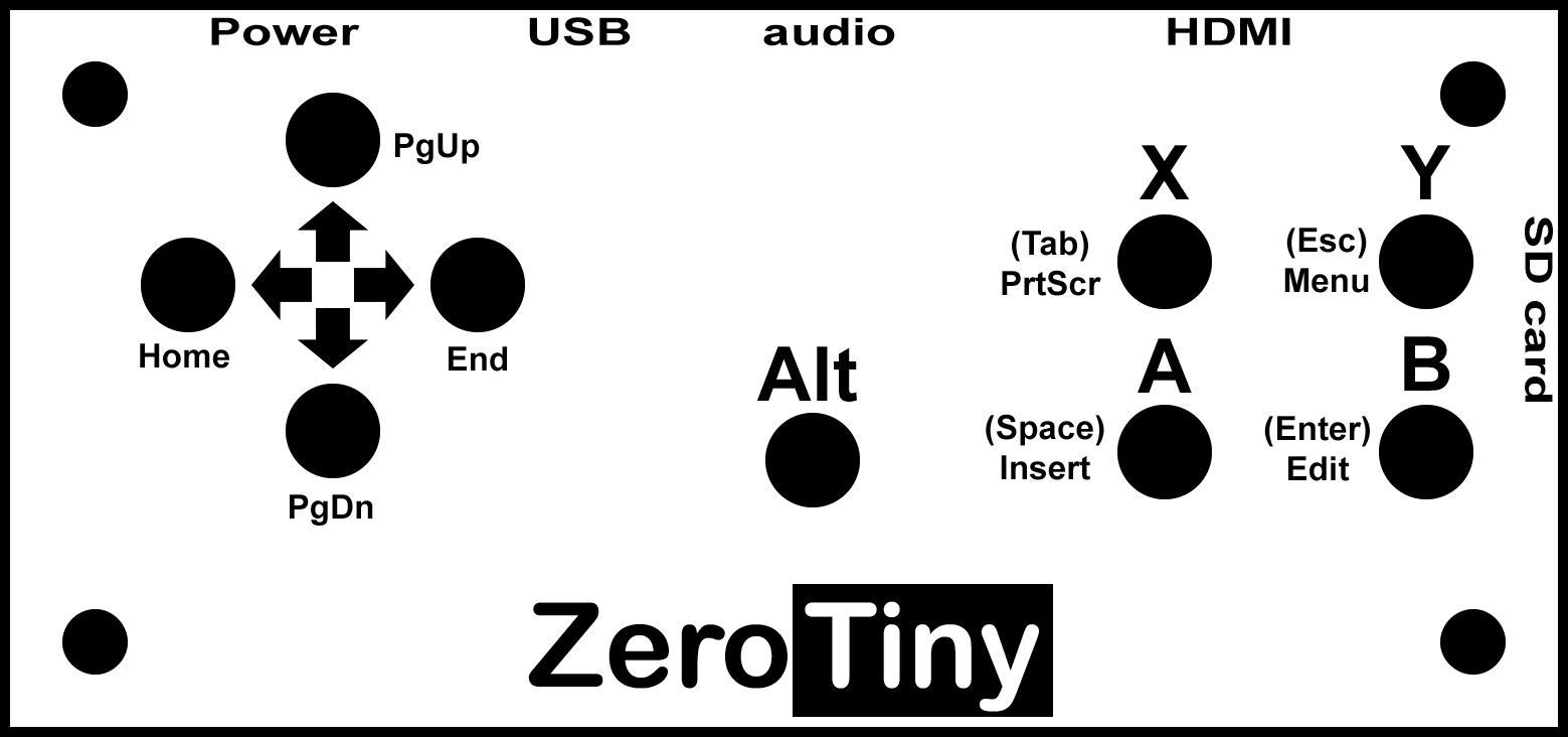
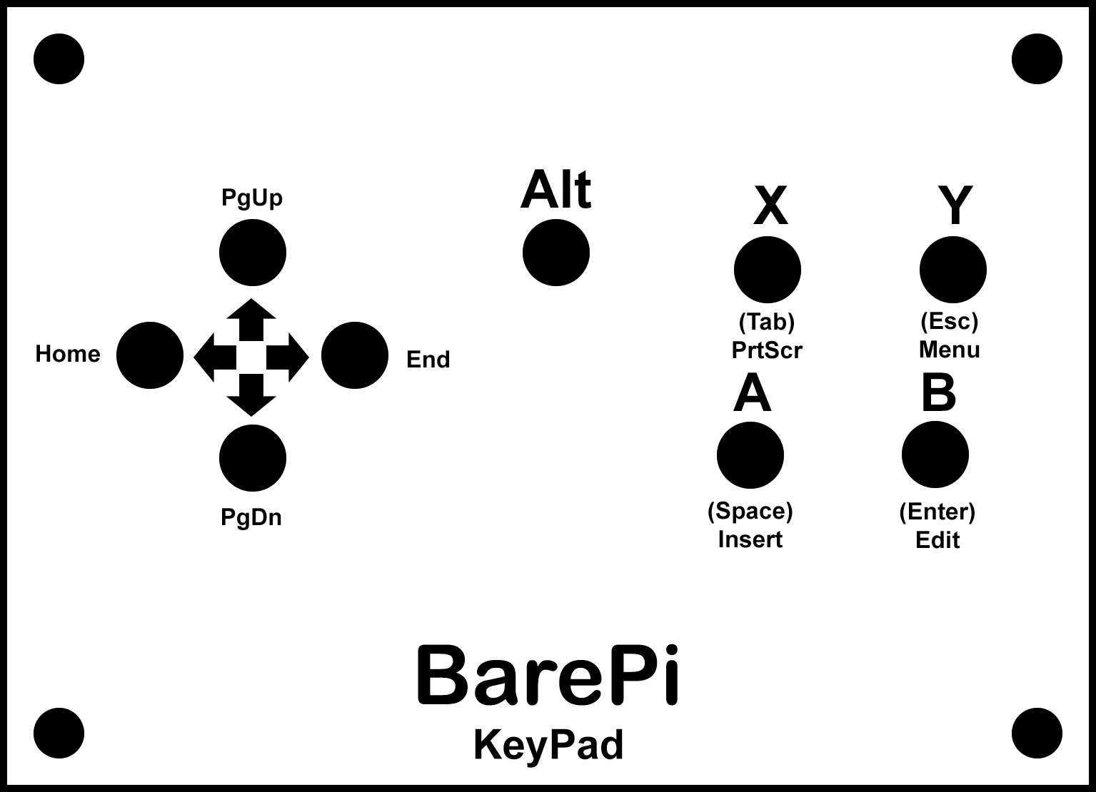
KeyPad (basic gaming keyboard with 9 buttons)
MiniKey (minimalist alphanumeric keyboard)
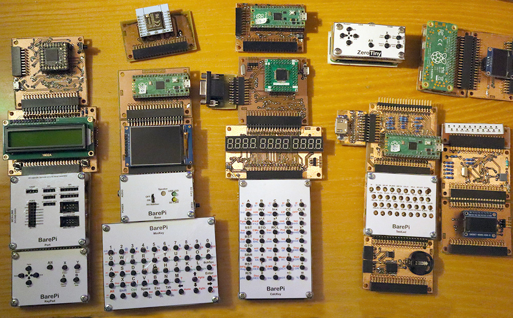
BarePi is a modular microchip kit designed for programming small devices such as game consoles or calculators. The main focus is on the Raspberry Zero 2 module, programmed as bare-metal (i.e. without an operating system) with library PiLibSDK (link www, GitHub). However, other types of processors supporting 3.3V signals can also be used (ATmega, CH32V, ESP32). The modules of the kit are connected via 40-pin connectors, forming a bus with signals defined according to the Raspberry Zero 2 module. The connectors ensure sufficient connection strength, no additional mechanical connections are needed. Most modules are pass-through - they contain both a bus input connector on the top edge of the board and a bus output connector on the bottom edge of the board. The exceptions are the processor modules, which contain only an output connector, and the alphanumeric keyboard module, which has only an input connector.
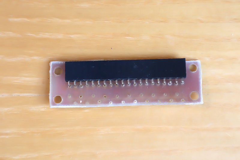
The connection connector consists of a 2x20-pin female header on the bottom of the module (signal output from the module - e.g. processor module) and a 2x20-pin pin header on the top of the module (signal input to the module - e.g. keyboard). Most modules have a width of 65 millimeters, based on the width of the Raspberry Zero 2 module. Most devices contain a processor module, a "Base" module with power supply and sound output, a display module and a keyboard module. All signals on the bus are at 3.3V levels. The bus also contains a 5V supply voltage, but this voltage is used both to supply power to the device (followed by a 3.3V stabilizer) and as a voltage for a possible signal converter to the 5V level. The 5V level must not be applied to the signal wires themselves, in many cases this could damage the device.
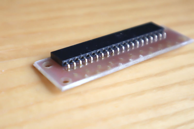
When building modules, you can solder the processor and display modules hard over the pin strip, but I recommend using a socket strip for easy replacement. The kit modules can be used in the simplest form, just the printed circuit board itself, but it is more luxurious to add a top panel. For some modules, such as the keyboard, the top panel is necessary because of the key labels. An additional printed circuit board can be used as the top panel, screwed to the module using spacers. The materials also include graphics for the bottom panel, but it is probably unnecessary - the bottom side of the module can be treated, for example, by gluing foam strips from window insulation so that the bottom side of the printed circuit board does not scratch the table. For the kit prototypes, instead of the top panel, I used only printed cardboard paper, covered with insulating tape against abrasion and with holes punched with a leather punch. For keyboards, I recommend adjusting the height of the keys so that the keycaps protrude 1 mm above the surface of the top panel. If the protrusion is too large, the keys may press into your fingers when pressed, and if the protrusion is too small, more force may be required to press.
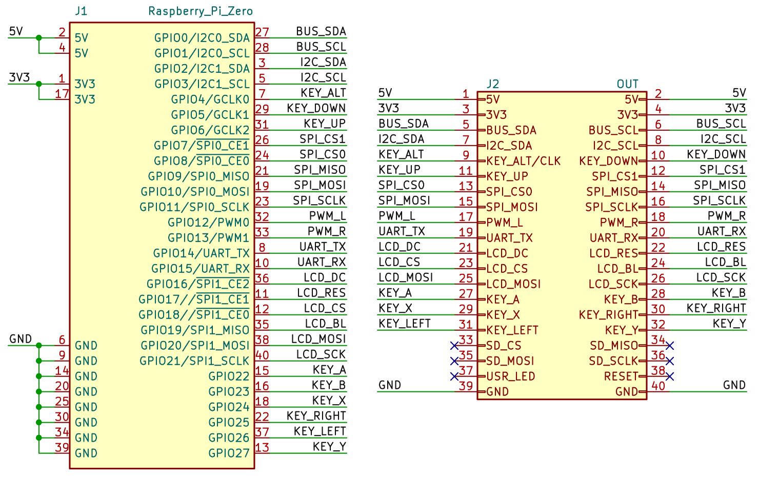
Definition of the signals on the bus connector, looking at the header strip on the bottom edge of the module. The corresponding GPIO pin number of the Raspberry Zero 2 module is shown in parentheses.
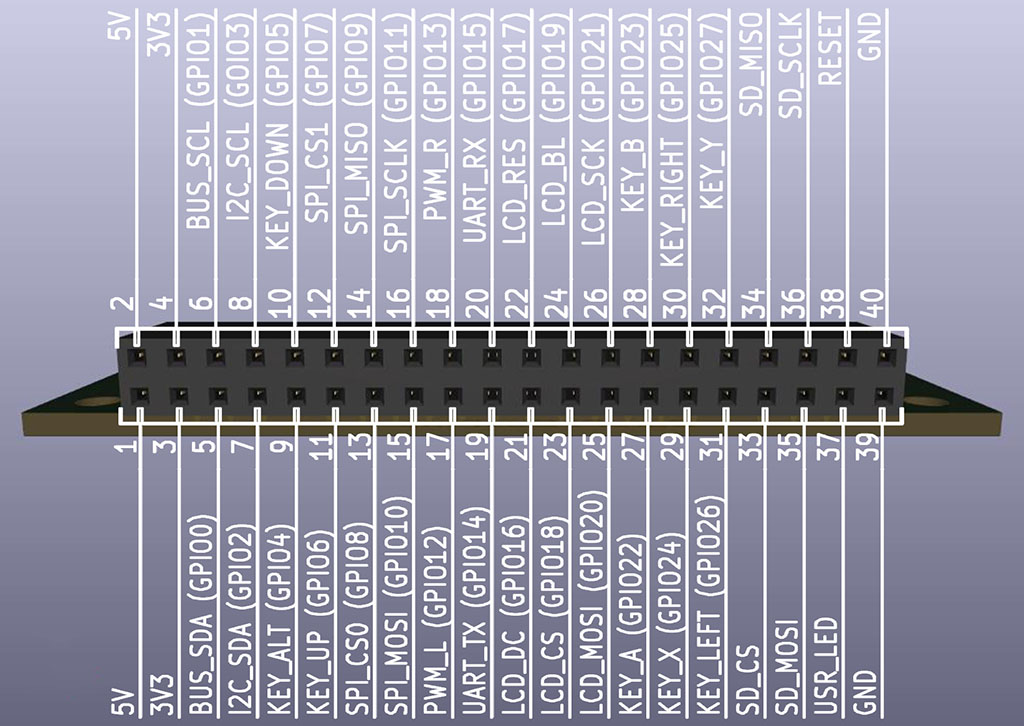
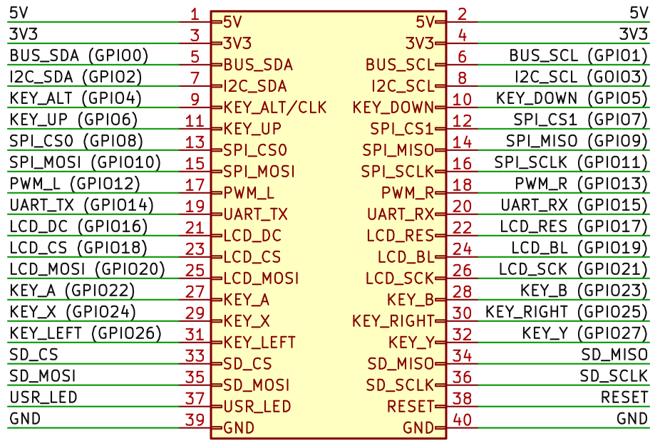
1,2 5V ... Supply voltage 5V. It is used to power the device, e.g. from a USB connector or a 3.7V battery. The device itself is powered by a voltage of 3.3V, so the device must also include a voltage stabilizer for 3.3V. All signals on the bus are at 3.3V levels. If signals with a 5V level are needed, a level converter must be used.
3,4 3V3 ... Supply voltage 3.3V. This is the main supply voltage of the device. It can be obtained by a stabilizer from a 5V voltage (e.g. from a USB connector) or a voltage converter from a battery.
5 BUS_SDA (GPIO0) ... Internal I2C bus data wire. The internal I2C bus is used to directly control the modules of the kit. The internal I2C bus can be a separate bus, separated from the external user I2C bus, so that the user can independently control the communication. In the Raspberry Zero 2 module, this is the I2C0 bus. In other modules, the internal I2C bus can be shared with the external I2C bus. In the Raspberry Zero 2 module, the I2C0 bus is also used to access the system ID EEPROM memory when the device is turned on - this must be remembered to avoid overlapping the functions of the EEPROM memory. The signal is of the open collector type - pull-up resistors must be used.
6 BUS_SCL (GPIO1) ... Clock wire of the internal I2C bus. In the Raspberry Zero 2 module this is the I2C0 bus. The signal is of the open collector type - pull-up resistors must be used.
7 I2C_SDA (GPIO2) ... External I2C bus data wire. The external I2C bus is used to control user devices so that communication does not conflict with the control of the kit modules. In the Raspberry Zero 2 module, this is the I2C1 bus. In other modules, the external I2C bus may be shared with the internal I2C bus. The signal is of the open collector type - pull-up resistors must be used.
8 I2C_SCL (GPIO3) ... Clock wire of external I2C bus. In Raspberry Zero 2 module this is I2C1 bus. Signal is open collector type - pull-up resistors must be used.
9 KEY_ALT (GPIO4) ... Input of the alternative function button "ALT". The button changes the meaning of the other keyboard keys. The button connects the pin to GND and requires the use of a pull-up resistor. This signal can also have other functions if the button function is not used. The clock signal from the processor can be output to the pin - in the Raspberry Zero 2 module this is the GPCLK0 signal. For this reason, the "ALT" button should be connected via a protective resistor (e.g. 1K0), which will prevent damage to the circuits if the button is accidentally pressed if the clock signal is output to the pin. Another additional function of the pin is the input of the ADC converter - typically in the Raspberry Pico and CH32 modules.
10 KEY_DOWN (GPIO5) ... "DOWN" button input. Along with the "ALT" button, it has an alternative meaning of "Page Down". The button connects the pin to GND and requires the use of a pull-up resistor.
11 KEY_UP (GPIO6) ... "UP" button input. Along with the "ALT" button, it has an alternative meaning of "Page Up". The button connects the pin to GND and requires the use of a pull-up resistor.
12 SPI_CS1 (GPIO7) ... The second SPI bus select signal. In the Raspberry Zero module, this is the SPI0 bus.
13 SPI_CS0 (GPIO8) ... The first SPI bus select signal. In the Raspberry Zero module, this is the SPI0 bus.
14 SPI_MISO (GPIO9) ... SPI bus MISO signal - data input to the processor from the peripheral (RX signal). In the Raspberry Zero module, this is the SPI0 bus. In some devices, the SPI bus may be shared with the SD card - in this case, it is necessary to remove the SD card from the slot before using the SPI bus.
15 SPI_MOSI (GPIO10) ... SPI bus MOSI signal - data output from the processor to the peripheral (TX signal). In the Raspberry Zero module, this is the SPI0 bus.
16 SPI_SCLK (GPIO11) ... SPI bus clock signal. In the Raspberry Zero module, this is the SPI0 bus.
17 PWM_L (GPIO12) ... Left channel audio output. Typically PWM modulation, so an RC filter may be required.
18 PWM_R (GPIO13) ... Right channel audio output. Typically PWM modulation, so an RC filter may be required.
19 UART_TX (GPIO14) ... Serial data output of the UART port. In some modules, this pin can be used as a CAN Bus serial data output (CAN_TX signal).
20 UART_RX (GPIO15) ... Serial data input of the UART port. In some modules, this pin can be used as a CAN Bus serial data input (CAN_RX signal).
21 LCD_DC (GPIO16) ... Control signal for LCD SPI display - resolution of data and control code.
22 LCD_RES (GPIO17) ... Signal to reset the LCD SPI display controller.
23 LCD_CS (GPIO18) ... Signal for selecting the LCD SPI display. In the Raspberry Zero module, this is the SPI1 bus. The PCM_CLK signal for the I2S/PCM interface can optionally be available on this pin.
24 LCD_BL (GPIO19) ... Signal for controlling the brightness of the LCD SPI display backlight. Typically, this is a PWM signal. Optionally, the PCM_FS signal for the I2S/PCM interface can be available on this pin. If the processor does not allow smooth brightness control, this pin should be HIGH for full display brightness.
25 LCD_MOSI (GPIO20) ... Serial data output to the LCD SPI display. In the Raspberry Zero module, this is the SPI1 bus. The PCM_DIN signal for the I2S/PCM interface can optionally be available on this pin.
26 LCD_SCK (GPIO21) ... LCD SPI display clock signal. In the Raspberry Zero module, this is the SPI1 bus. Optionally, the PCM_DOUT signal for the I2S/PCM interface can be available on this pin.
27 KEY_A (GPIO22) ... Input button "A" - the main action button. On the alphanumeric keyboard, it corresponds to the "Spacebar" key. Together with the "ALT" button, it has an alternative meaning of "Zoom" - switching the view on the built-in LCD display. The button connects the pin to GND and requires the use of a pull-up resistor.
28 KEY_B (GPIO23) ... "B" button input - secondary action button. On an alphanumeric keyboard, it corresponds to the "Enter" key. Together with the "ALT" button, it has an alternative meaning of "Insert". The button connects the pin to GND and requires the use of a pull-up resistor.
29 KEY_X (GPIO24) ... Input button "X" - additional functions button (e.g. help). On the alphanumeric keyboard it corresponds to the "Tab" key. Together with the "ALT" button it has an alternative meaning "Print Screen" - screenshot of the screen contents to a file. The button connects the pin to GND and requires the use of a pull-up resistor.
30 KEY_RIGHT (GPIO25) ... "RIGHT" button input. Along with the "ALT" button, it has an alternative meaning of "End". The button connects the pin to GND and requires the use of a pull-up resistor.
31 KEY_LEFT (GPIO26) ... "LEFT" button input. Along with the "ALT" button, it has an alternative meaning of "Home". The button connects the pin to GND and requires the use of a pull-up resistor.
32 KEY_Y (GPIO27) ... "Y" button input - interrupt, exit or menu button. On an alphanumeric keyboard, it corresponds to the "Esc" key. Together with the "ALT" button, it has an alternative meaning of "Menu", invoking the system menu. The button connects the pin to GND and requires the use of a pull-up resistor.
33 SD_CS ... SPI signal for selecting the SD card. An LED indicating access to the SD card can be connected to this signal.
34 SD_MISO ... SPI data input from SD card to processor.
35 SD_MOSI ... SPI data output from the processor to the SD card.
36 SD_SCLK ... SPI clock for SD card.
37 USR_LED ... Output to user LED. Active signal is HIGH.
38 RESET ... "RESET" button input for resetting the processor. The button connects the pin to GND and requires the use of a pull-up resistor. For some modules, the pull-up resistor is internally part of the module.
39, 40 GND ... Ground 0V.
In most modules, the I2C bus signals are equipped with a 15K pull-up resistor. This value should ensure reliable bus operation with 1 to 5 connected devices. The BarePi kit modules use the following I2C addresses:
0x30 ... LCD
SPI graphics display (LCD320x240, LCD160x80)
0x31 ... LCD text display (LCD16x2)
0x32 ... LED 7-segment display (LED12)
0x34 ... alphanumeric keyboard (MiniKey)
0x35 ... calculator keyboard (CalcKey)
0x38 ... PORT interface (Port module)
0x3C ... OLED display SSD1306
0x50-0x56 ... EEPROMs
0x57 ... configuration EEPROM 4KB AT24C32
0x68 ... RTC clock DS3231
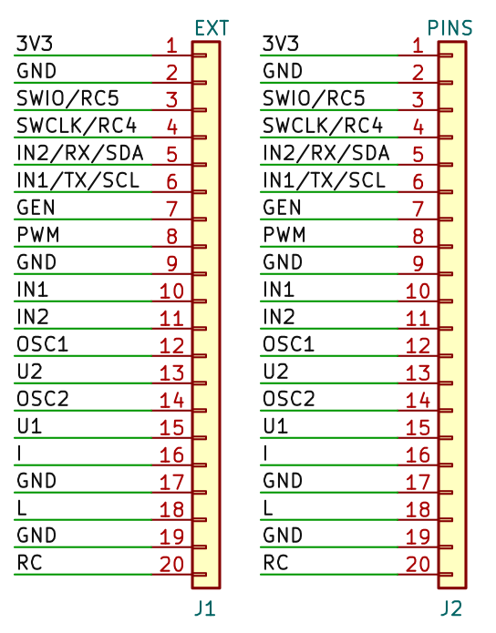
Some modules allow image output to an external display with a VGA or HDMI interface. These modules contain a 2x10-pin female header connector that contains signals for output to both an HDMI display and a VGA display. In addition, the connector contains a signal used to detect whether a DispHDMI, DispVGA module is inserted into the connector or the connector is left free. Accordingly, the interface for an HDMI display, a VGA display or an internal LCD display can be selected.
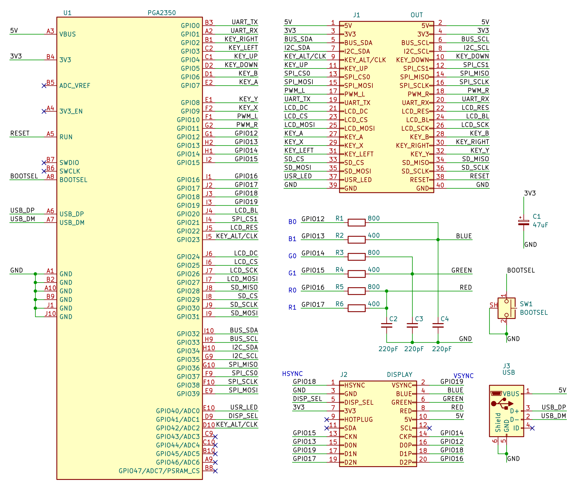
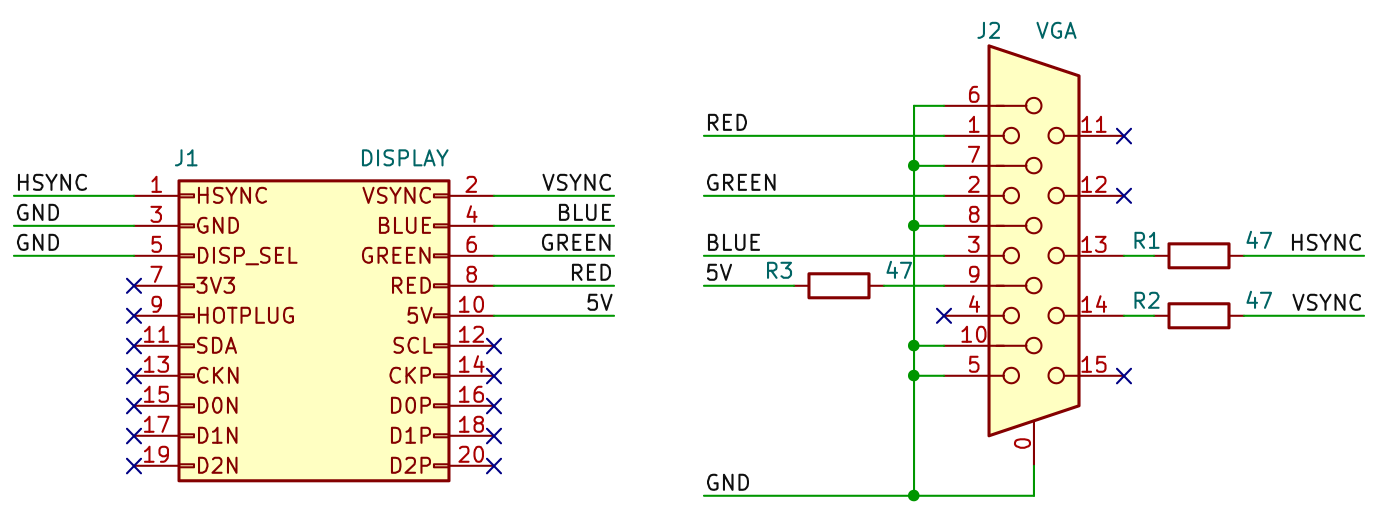
Definition of the signals on the display connector, looking at the female header strip at the output of the processor module. The corresponding GPIO pin number of the PGA2350 module is shown in parentheses.
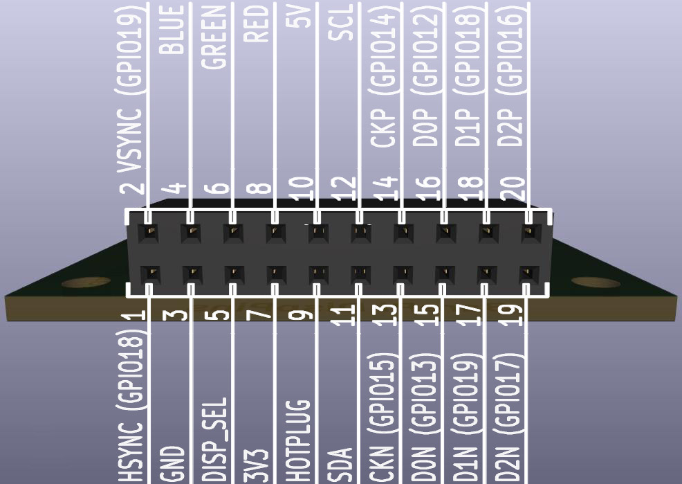
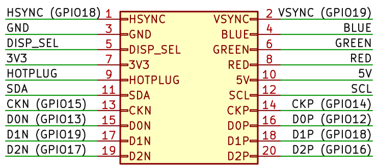
1 HSYNC (GPIO18) ... Horizontal synchronization of the VGA display. The signal is protected in the DispVGA adapter by the 47 ohm resistor to limit current surge on long wires.
2 VSYNC (GPIO19) ... Vertical synchronization of the VGA display. The signal is protected in the DispVGA adapter by the 47 ohm resistor to limit current surge on long wires.
3 GND ... Ground 0V.
4 BLUE ... Blue color component for VGA display.
5 DISP_SEL ... Detection of connected adapter. The signal is connected to GND in the DispVGA adapter, to 3V3 in the DispHDMI adapter. If no adapter is inserted, the signal is not connected to any wire - in this configuration, an internal LCD display can be used. In some devices, in this third state, autodetection of the connected VGA or HDMI monitor type is performed - by testing the impedance on the VGA connector. However, it is not recommended to use autodetection, as it is not reliable enough.
6 GREEN ... Green color component for VGA display.
7 3V3 ... Supply voltage 3.3V. Reserved for pull-up resistors of the DispHDMI adapter, currently not used.
8 RED ... Red color component for VGA display.
9 HOTPLUG ... HDMI monitor connection detection. If an HDMI monitor is connected and ready to receive a signal, it sets the HOTPLUG signal to HIGH. During normal operation, the device will only start transmitting the image when the HOTPLUG signal is set. The signal is usually +5V, so a resistor divider is used in the DispHDMI adapter to reduce the voltage to 3.3V. Currently, no modules in the kit use the HOTPLUG signal; the image is transmitted independently of the monitor connection.
10 5V ... Supply voltage 5V. The voltage is used to power the monitor's communication circuits, to power display adapters (e.g. VGA to HDMI converter) and to power the monitor's configuration EEPROM. The current is limited by a 47 ohm protective resistor in the adapters.
11 SDA ... I2C bus data signal used to read EDID data from an HDMI monitor. Currently, no kit modules use this signal. Be careful when using it - on most monitors the signal is connected via a pull-up resistor to +5V, which can be dangerous for circuits operating at 3.3V levels.
12 SCL ... I2C bus clock signal used to read EDID data from HDMI monitor. Currently, no kit modules use this signal. Be careful when using it - on most monitors the signal is connected via a pull-up resistor to +5V, which can be dangerous for circuits operating with 3.3V levels.
13 CKN (GPIO15) ... CK- signal for HDMI display. The signal is limited by a 270 ohm resistor in the HDMI adapter.
14 CKP (GPIO14) ... CK+ signal for HDMI display. The signal is limited by a 270 ohm resistor in the HDMI adapter.
15 D0N (GPIO13) ... D0- signal for HDMI display. The signal is limited by a 270 ohm resistor in the HDMI adapter.
16 D0P (GPIO12) ... D0+ signal for HDMI display. The signal is limited by a 270 ohm resistor in the HDMI adapter.
17 D1N (GPIO19) ... D1- signal for HDMI display. The signal is limited by a 270 ohm resistor in the HDMI adapter.
18 D1P (GPIO18) ... D1+ signal for HDMI display. The signal is limited by a 270 ohm resistor in the HDMI adapter.
19 D2N (GPIO17) ... D2- signal for HDMI display. The signal is limited by a 270 ohm resistor in the HDMI adapter.
20 D2P (GPIO16) ... D2+ signal for HDMI display. The signal is limited by a 270 ohm resistor in the HDMI adapter.
The BarePi kit uses a uniform structure in its EEPROM configuration memories and register-controlled devices, facilitating access to data and control registers. The EEPROMs used in the BarePi kit, as well as the module controllers, are controlled via the I2C bus, typically operating at 100 kHz. The module controllers typically contain a CH32V-series processor, which is accessible via the I2C bus in a manner similar to EEPROM memory with 8-bit or 16-bit addressing. At the beginning of the memory space are the controller’s control and data registers, followed by the processor’s Flash memory, which can be used similarly to EEPROM memory to store configuration information. However, it is important to note that the processor’s Flash memory has a more limited number of write cycles than EEPROM memory - typically several thousand write cycles.
Memories ranging in size from 512 bytes to 64 KB are addressed using a 16-bit address. Memories of 256 bytes or less are addressed using an 8-bit address. This differs from traditional EEPROMs - memory blocks ranging from 512 bytes to 2 KB are typically originally addressed as 256-byte blocks across multiple I2C addresses. In BarePi, all memory blocks are addressed using a single I2C address, either in 8-bit or 16-bit mode, depending on their size. While the original 512B - 2KB EEPROMs can also be used, they can only be configured as multiple 256B memory blocks at multiple addresses.
To access the devices, I recommend using only the 100 kHz I2C speed. Higher speeds may be too much for the processors in the modules to handle reliably. The 16-bit memory cell address is in big-endian format (Motorola format), similar to the EEPROM memory address - that is, the high byte of the address is transmitted first, followed by the low byte. However, the data in the memories is in little-endian format (Intel format) - that is, the lower byte comes first, and at higher addresses, the higher byte comes first. Additionally, I recommend maintaining the alignment of entries (e.g., aligning a 16-bit word to an even address) so that the control processor can more easily access the record entries in its structures.
At the beginning of the EEPROM configuration memory and the device memory, there is a 4-byte header with identification:
- Memory offset 0: "BPi" ... 3 characters containing the magic text "BPi" (= "Bare Pi")
- Memory offset 3: "D" ... a character representing the total memory size: ('3'=8B, ... '9'=512B, 'A'=1KB, ... 'G'=64KB). This character can be used by the main processor to detect the memory size - but only in 16-bit mode, meaning memory sizes ranging from 512B to 64KB. Smaller memory sizes cannot be detected because 8-bit and 16-bit access modes cannot be mixed.
Configuration records begin at memory offset 4. Each record begins with a 4-byte header:
- Record offset 0: ... 2 bytes containing the record type identifier, in little-endian format (the lower byte is at the lower address). Values from 0x0001 to 0x00FF are reserved for internal use by the BarePi kit. The value 0x0001 denotes the device controller’s register array. The value 0x0002 indicates the device’s freely usable RAM. The value 0xFFFF indicates the end of records - before memory formatting, the memory is initialized to 0xFF and the header is written; the bytes 0xFF 0xFF following the header indicate the end of the record array.
- Record offset 2: ... 2 bytes containing the length of the following data (excluding the header).
The PiLisbSDK library for the Raspberry Zero 1/2 module includes the "drv_i2cbus.*" driver for easy access to memory and devices, enabling simple communication with devices on the I2C bus via a message queue. The "drv_eeprom.*" driver is available for easy use of entries in the configuration memory.
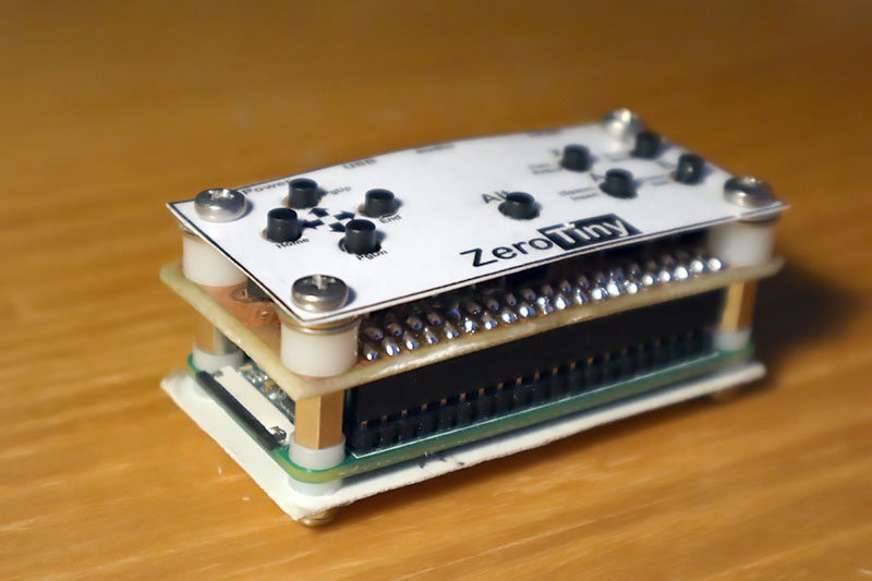
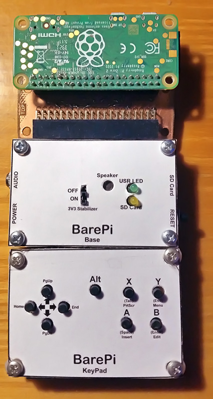
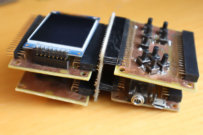
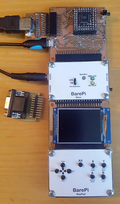
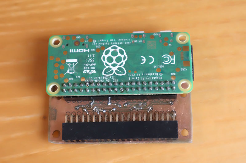
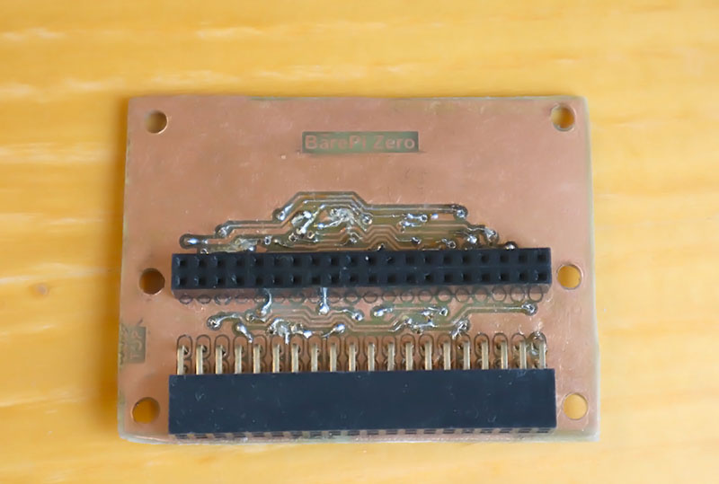
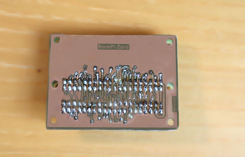
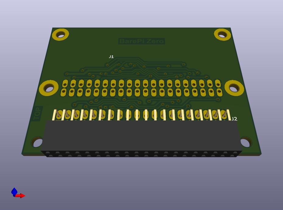
The game console "ZeroTiny" is not directly part of the BarePi kit. This is a minimalist game console with a Raspberry Zero 2 or Raspberry Zero 1 module. It is an example of creating an end device based on the modules of the kit. Its connection corresponds to the connection of the "Zero", "Base" and "KeyPad" modules. In the construction, I recommend using a female connector strip rather than direct soldering of the Zero module - so that the Zero 1 or Zero 2 modules can be exchanged. The ZeroTiny console in the PiLibSDK library, where you can also find sample applications: www, GitHub.

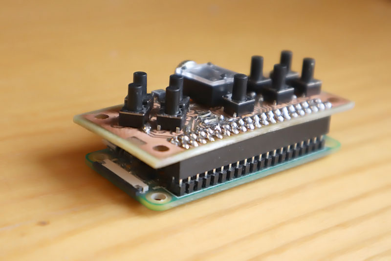
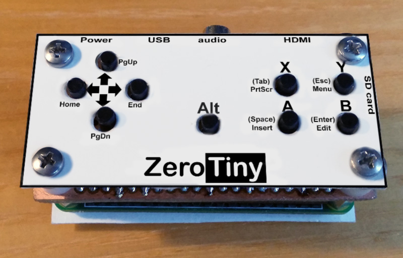
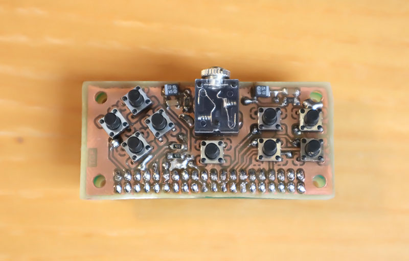
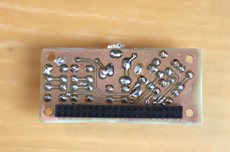
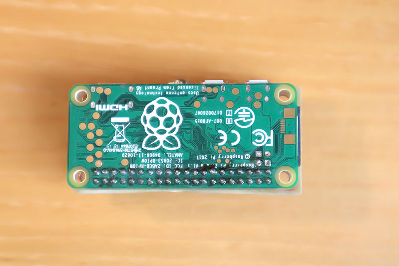
ZeroTiny console built from BarePi modules:
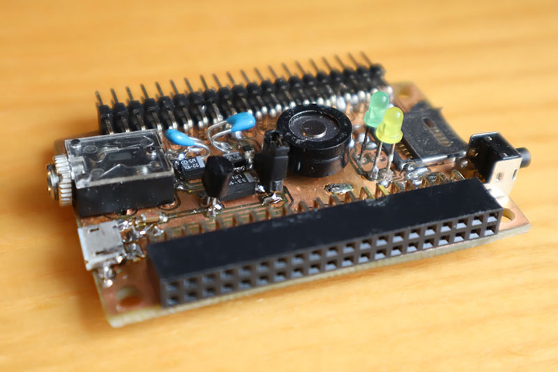
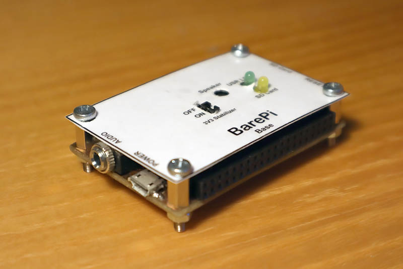
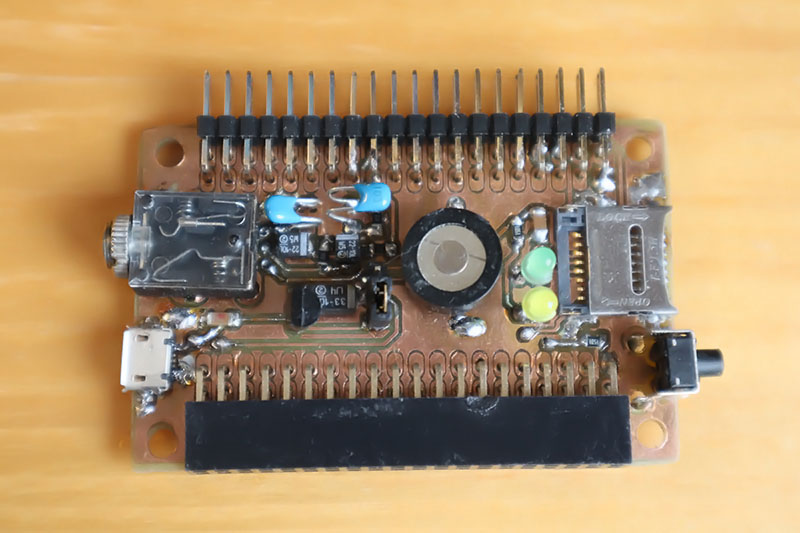
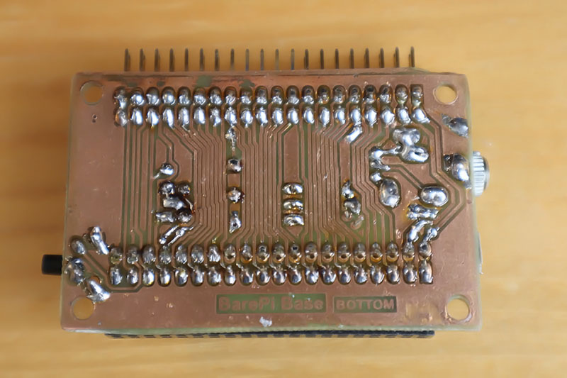
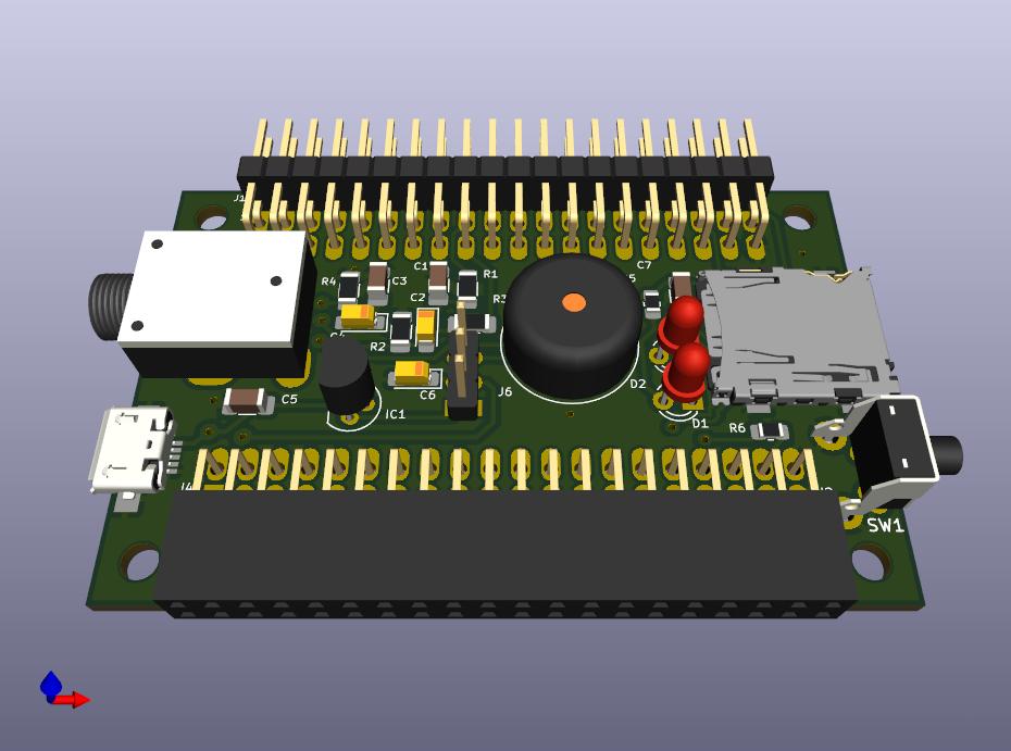
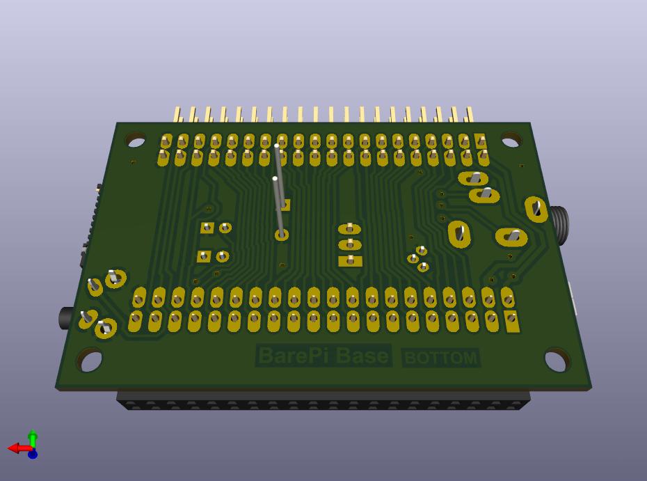
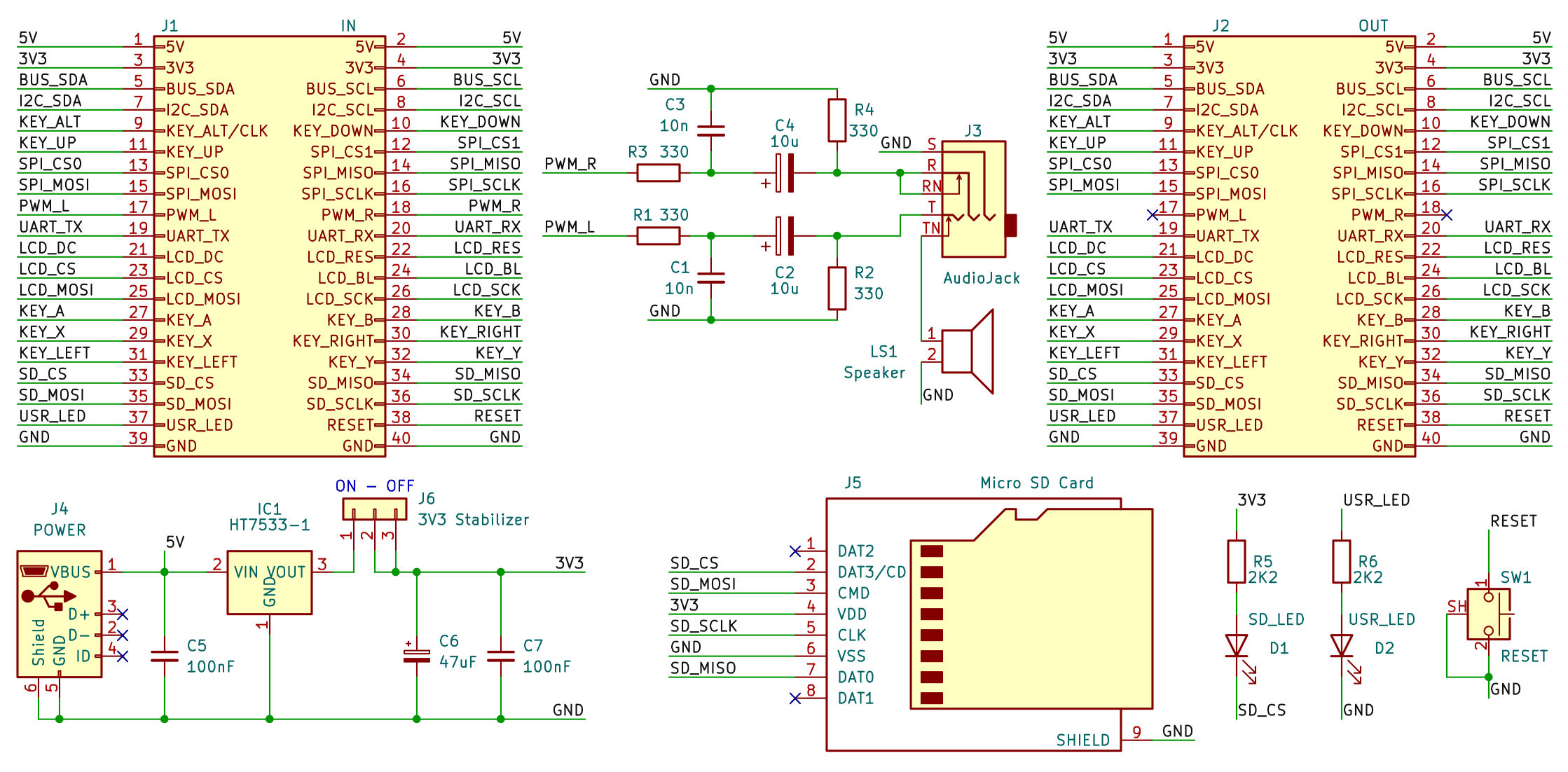
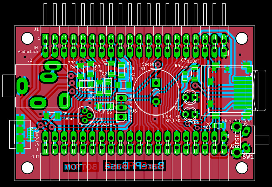
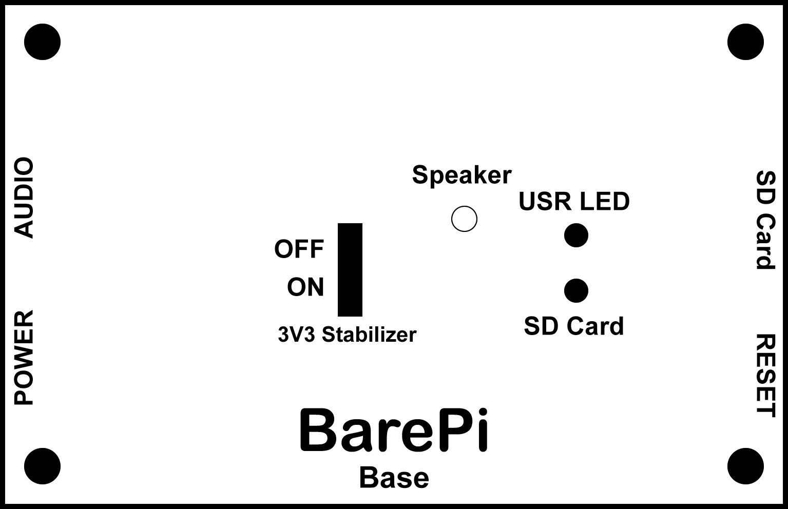
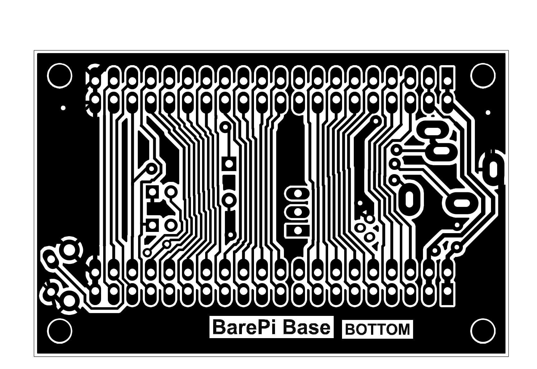
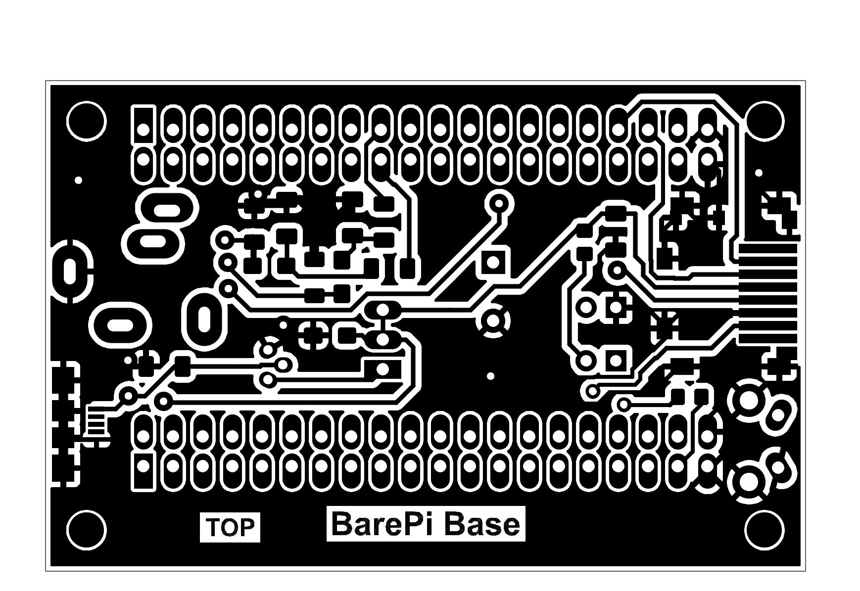
The "Base" module is the basic module of the kit. The module can be used with all devices - it provides power to the device from the USB connector (using a 3.3V stabilizer), audio output, microSD card slot, processor reset button, SD card access LED and user LED. Before manufacturing the PCB, check the definition for the audio connector, SD card slot, speaker and HT7533 stabilizer - the coordinates and meaning of the pins may vary from manufacturer to manufacturer. There is a jumper on the module that determines whether the internal 3.3V stabilizer is used. If the processor module contains its own stabilizer, it may be appropriate to turn off the stabilizer on the "Base" module. When constructing this module, I would like to point out that some components are too close together and are difficult to solder - it might be better to rearrange the board slightly and also choose larger housings for the capacitors. The speaker could also use some improvement - the sound is quiet, so an amplifier might be needed.
The PWM_L and PWM_R audio signals terminate in this module and do not continue beyond it. This is to minimize interference with the audio signal. If possible, connect the "Base" module first, immediately after the processor module. Better routing of the audio wires and more thorough shielding would likely improve the audio signal quality as well.
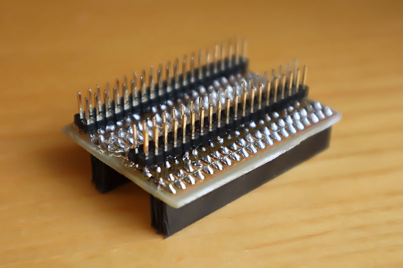
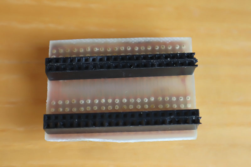
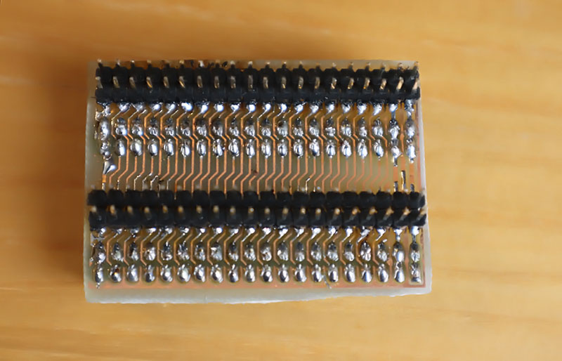
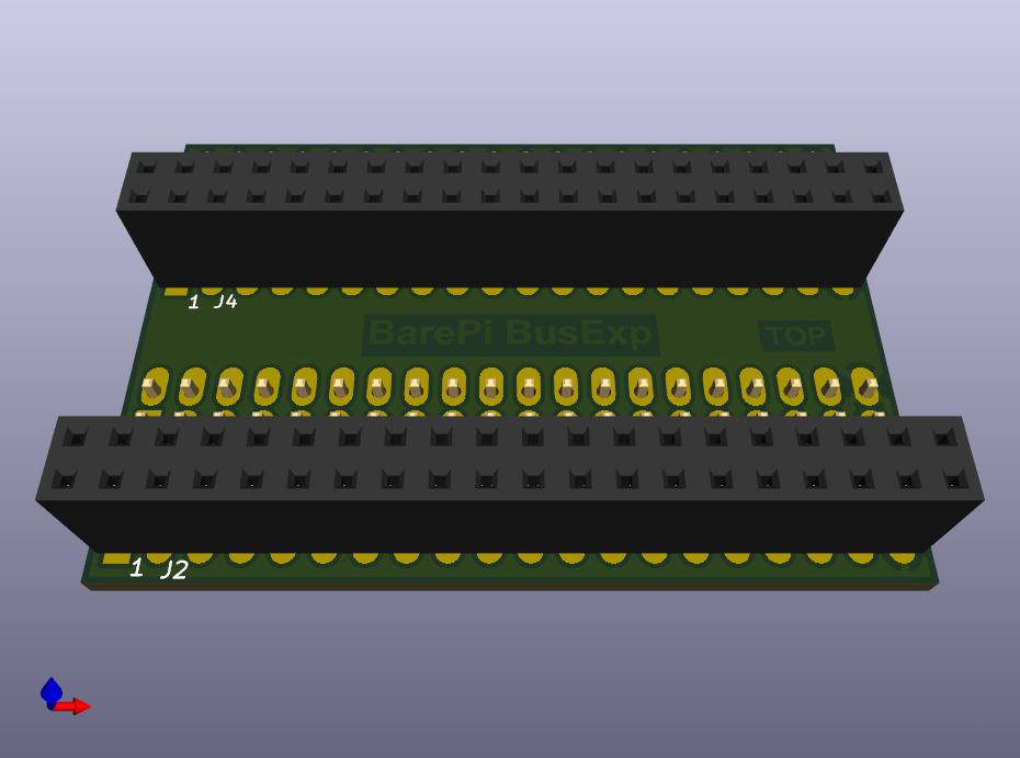
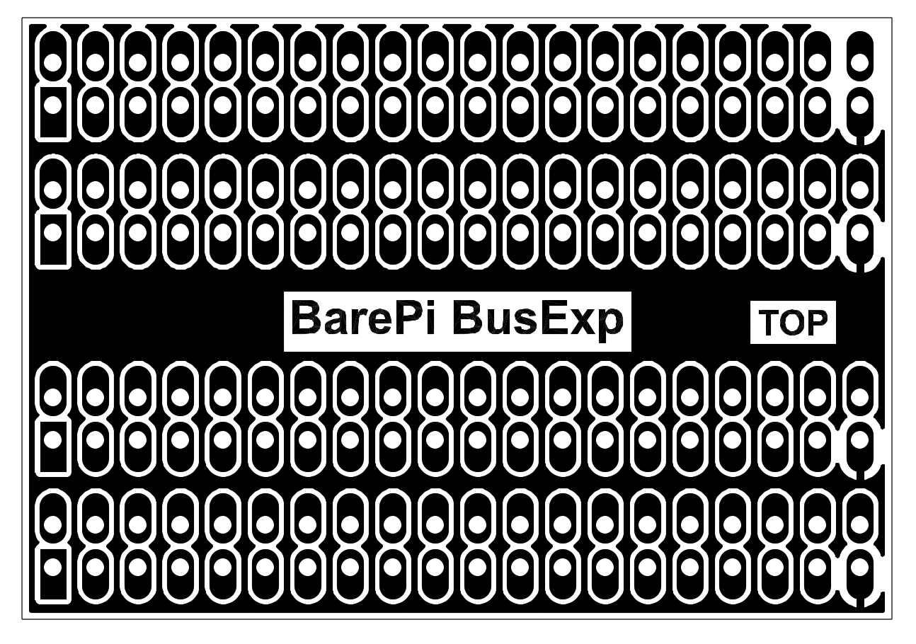
The "BusExp" module is a bus expander. It allows you to connect up to 4 modules together if you prefer to organize the modules "on top of each other" rather than "side by side".
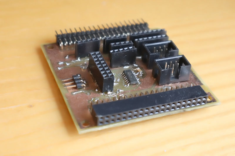
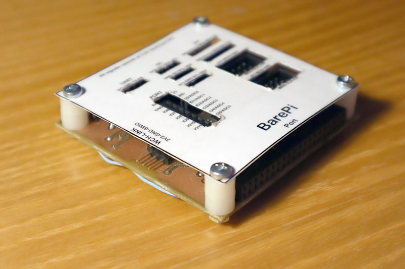
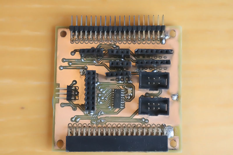
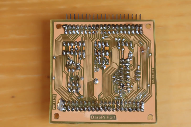
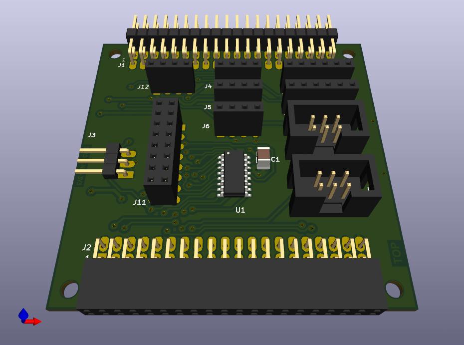
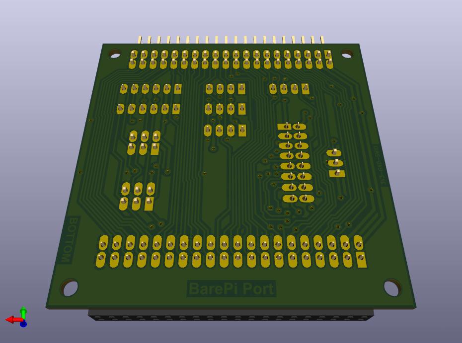
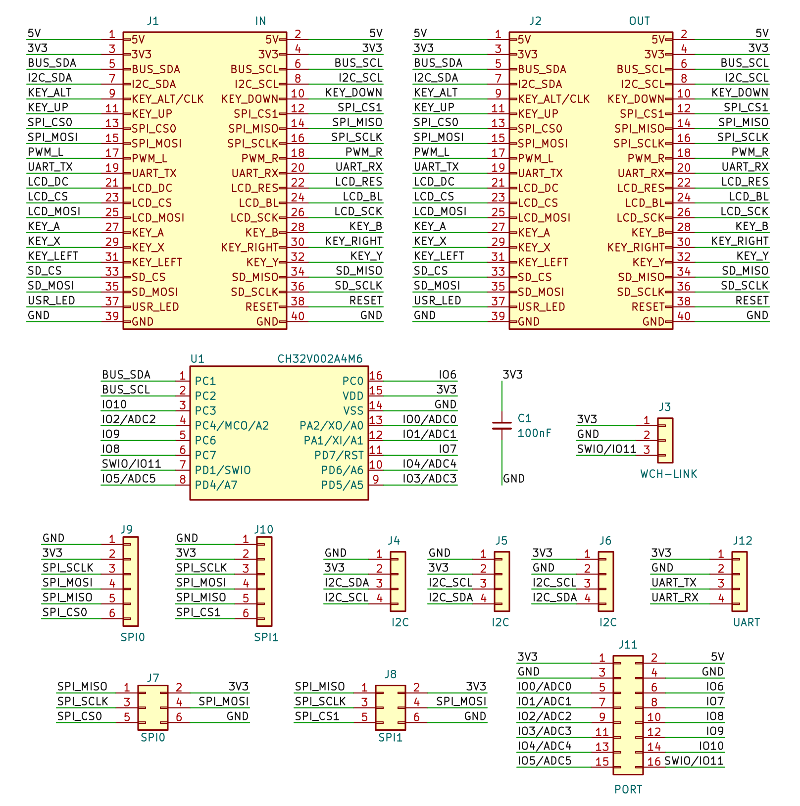
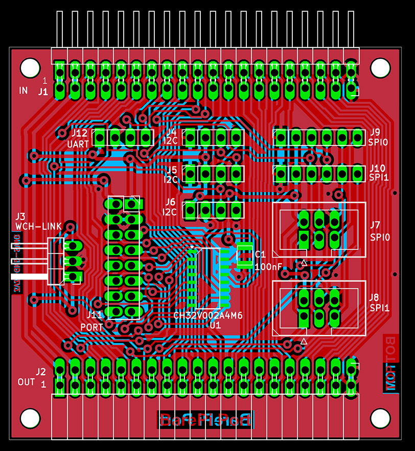
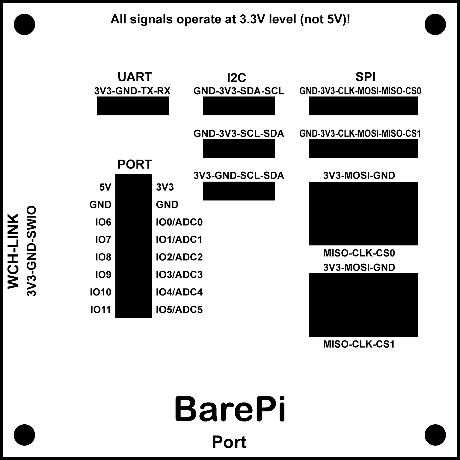
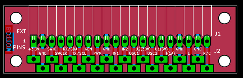
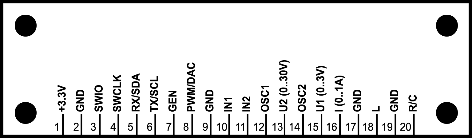
The "Port" module is a module for connecting external peripherals. It contains connectors for SPI, I2C, UART connections, as well as a CH32V002A4M6 processor, which provides 12 digital inputs/outputs and 6 analog ADC inputs. The processor is connected to the I2C bus at address 0x38.
You can find the processor firmware in the CH32LibSDK library in folder ch32\BAREPI\PORT12\ (GitHub: https://github.com/Panda381/CH32LibSDK/tree/main/ch32/BAREPI/PORT12 ).
In the PiLibSDK library, you'll find the device driver in drv_port12.* (GitHub: https://github.com/Panda381/PiLibSDK/tree/main/_drv ).
In the PiLibSDK library, you'll find the test program in Apps\TEST\PORT2 (GitHub: https://github.com/Panda381/PiLibSDK/tree/main/Apps/TEST/PORT12 ).
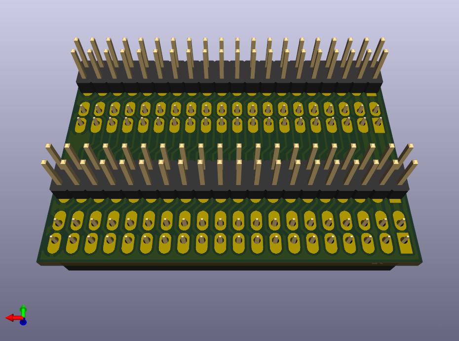
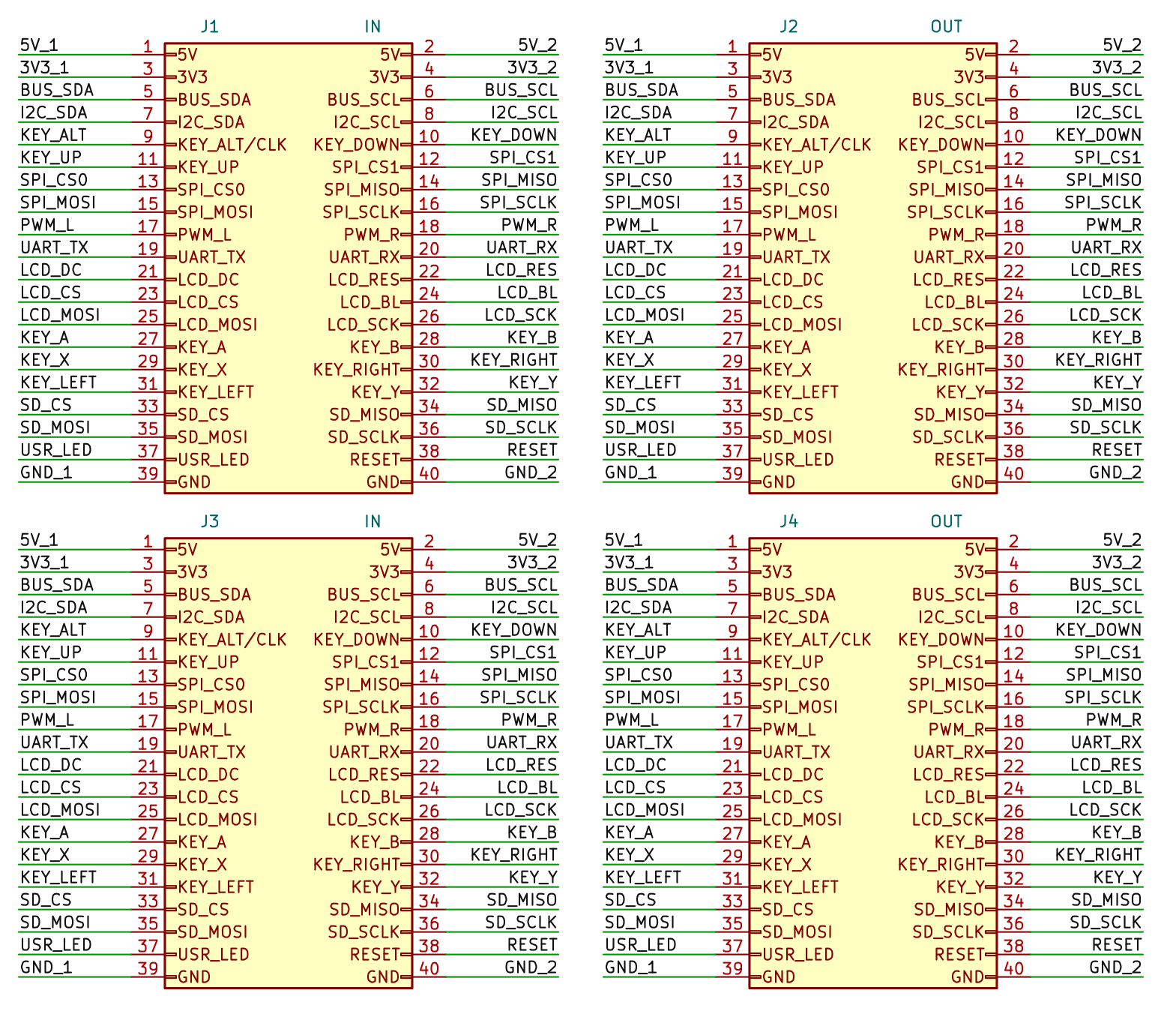
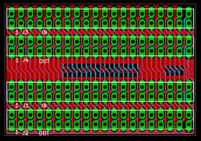
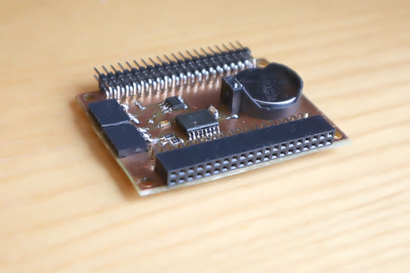
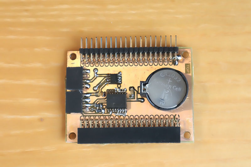
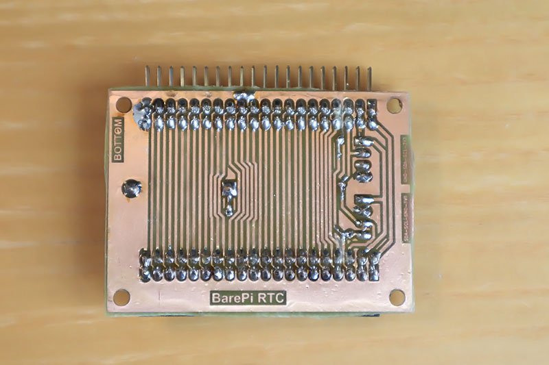
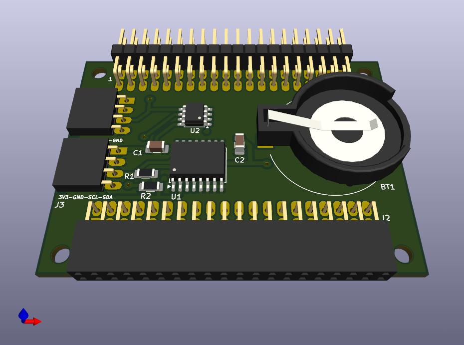
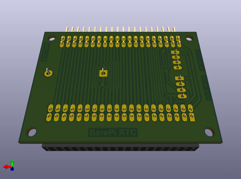
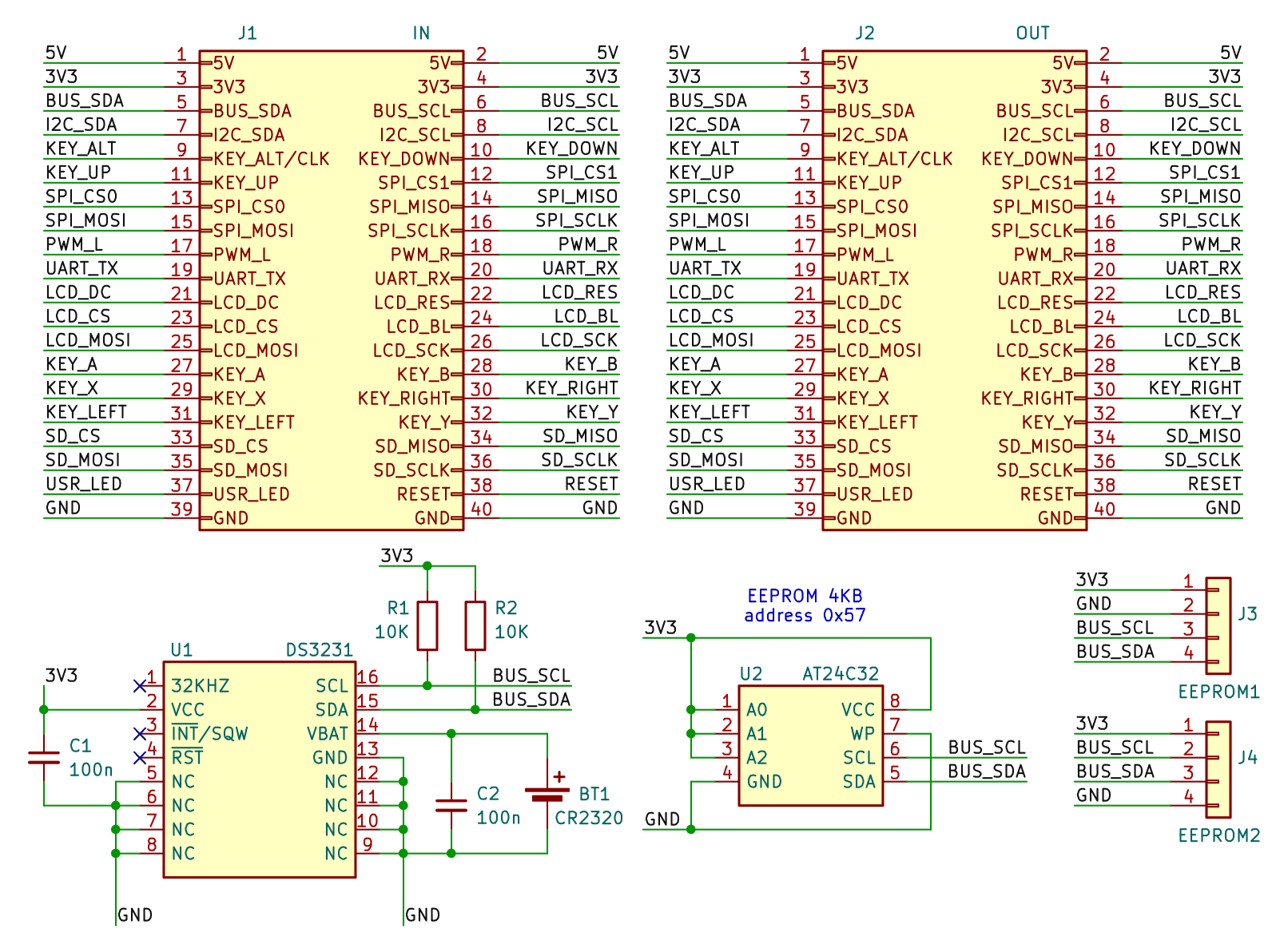
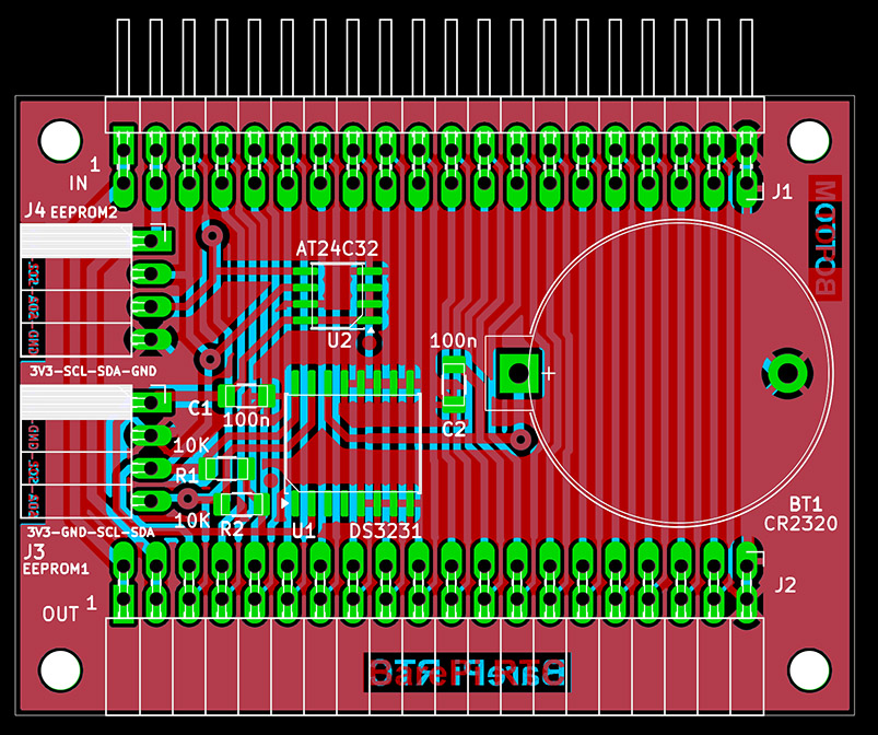
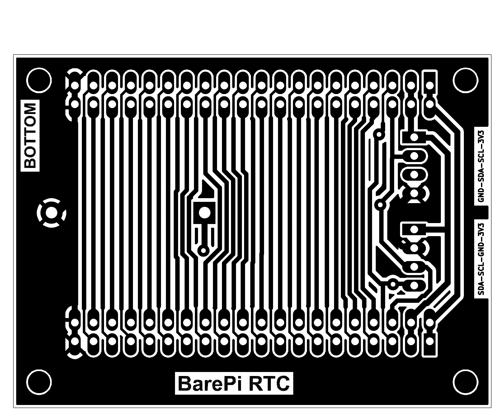
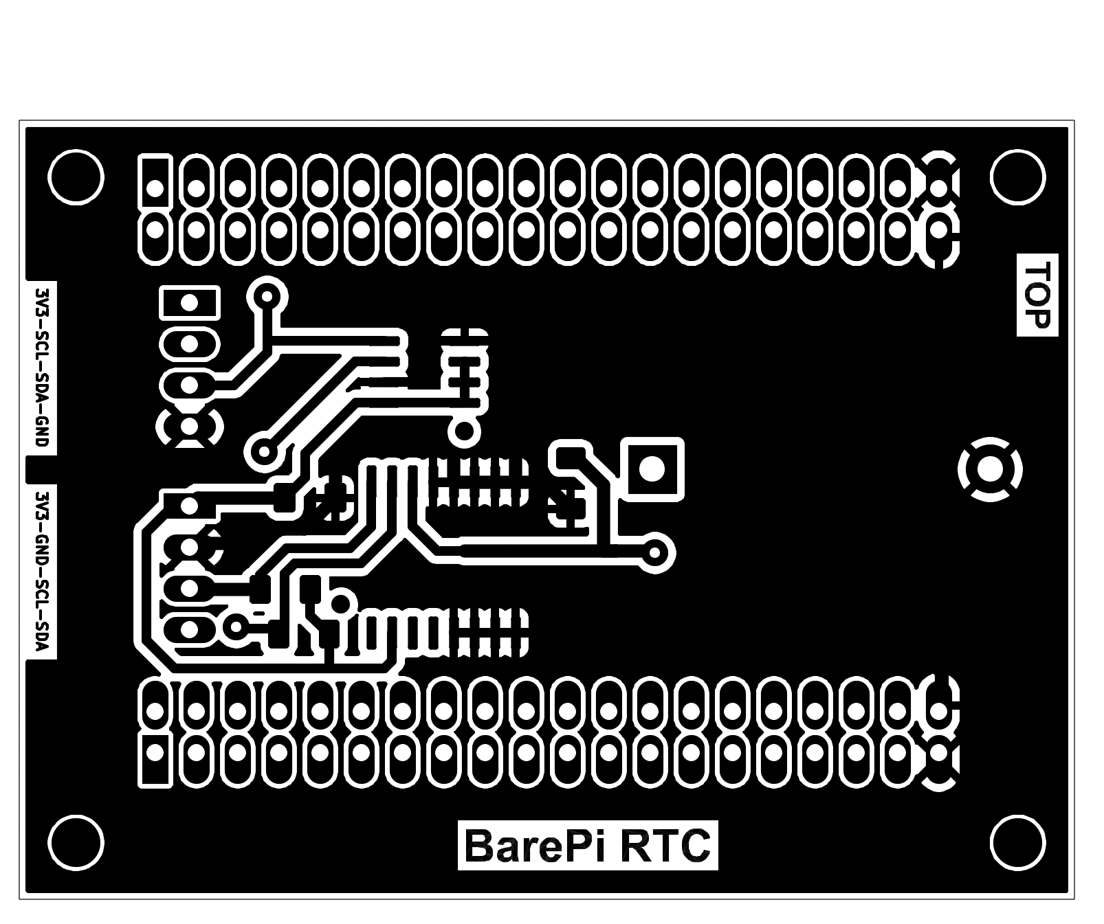
The "RTC" module is a module containing a real-time clock and EEPROM memory. The real-time clock is provided by the DS3231 circuit, backed up by a CR2032 battery. It is possible to use either the original MAXIM circuit or a much cheaper Chinese clone, which has lower accuracy, but its accuracy is sufficient for normal use. I personally used a commercially available real-time clock module, from which I soldered out the DS3231 circuit, the AT24C32 memory and the CR2032 battery holder, and used everything in this module. The "RTC" module contains a built-in AT24C32 EEPROM memory, with a capacity of 4KB, at I2C address 0x57. This memory is used to store program configurations. External modules with EEPROM memory with a capacity of up to 64KB can be connected to the module, in 2 different pinout configurations. An EEPROM module with a pinout of VCC-GND-SCL-SDA can be connected to the first slot, J3. The second slot, J4, is used to connect an EEPROM module with the pinout VCC-SCL-SDA-GND. Memory slots can have an I2C address of 0x50 to 0x56. For AT23C256 and AT23C512 memories, the address range can only be selected from 0x50 to 0x53. When using EEPROM memories, it is important to remember that Raspberry Pi modules (Zero, 1, 2, 3) use the I2C0 bus to read the EEPROM ID during startup, which is located at address 0x50. If the user EEPROM does not use the same data structure as the EEPROM ID, or the same address, this should not be a problem.
In the PiLibSDK library, in the _drv folder, the drv_rtc.* files contain a driver that allows reading and setting the current time in the DS3231 RTC module (GitHub: https://github.com/Panda381/PiLibSDK/tree/main/_drv ). If a DS3231 chip is detected on the I2C0 bus when the application starts, the current time is read from it. For I2C EEPROMs, a driver is available in the _drv folder in the drv_eeprom.* files. Using this driver, you can format the 4KB configuration EEPROM at address 0x57, as well as read and write configuration entries. Programs can store their configurations and records here using their own ID number. In the PiLibSDK library, you'll find a test program in Apps\TEST\RTC that you can use to display and set the current time (GitHub: https://github.com/Panda381/PiLibSDK/tree/main/Apps/TEST/RTC ).
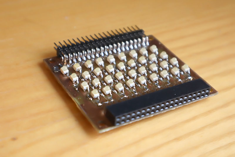
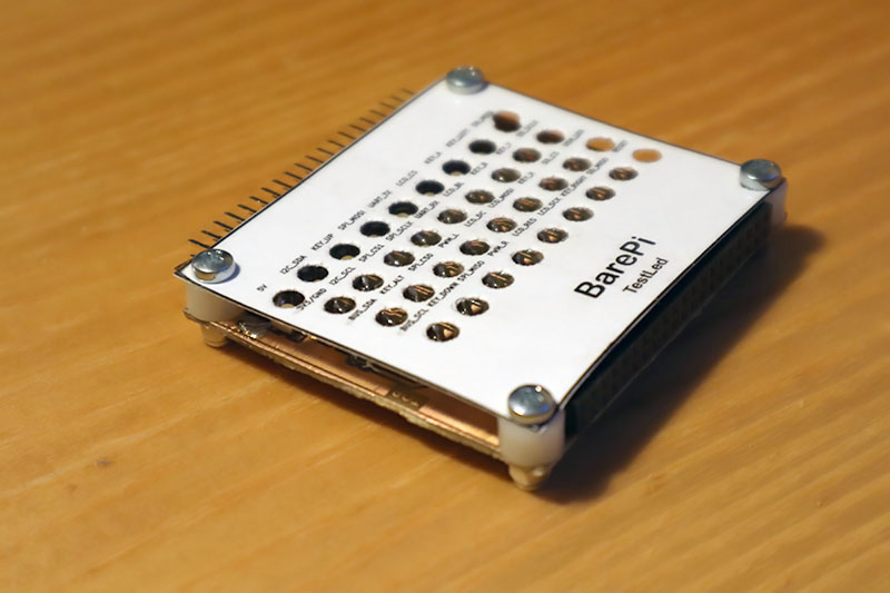
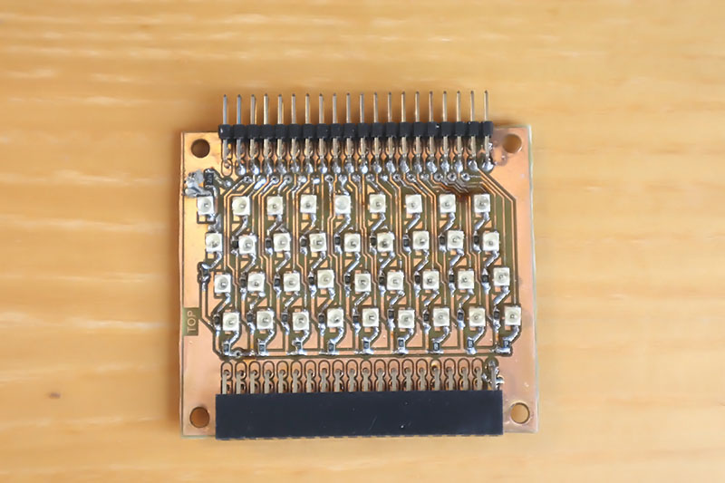
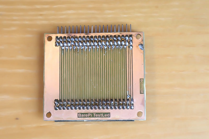
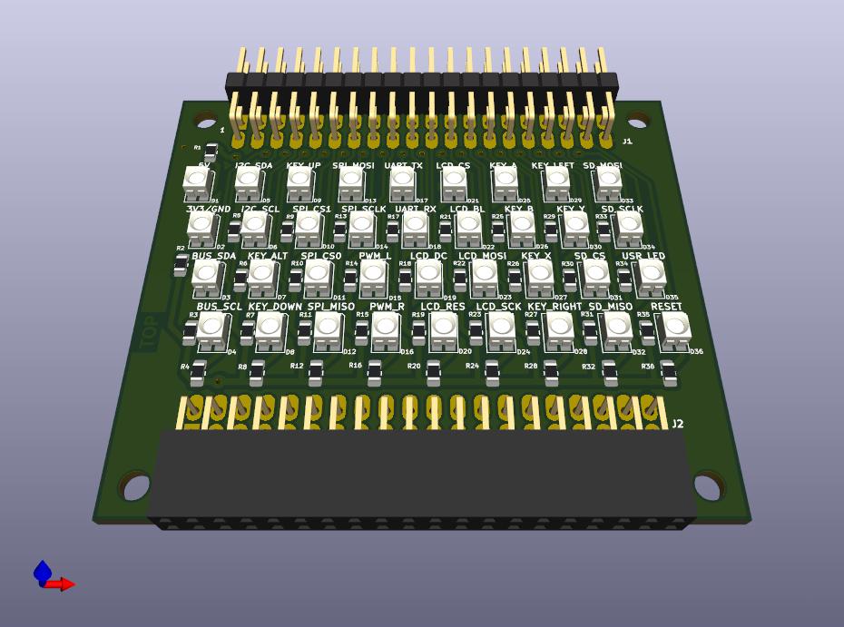
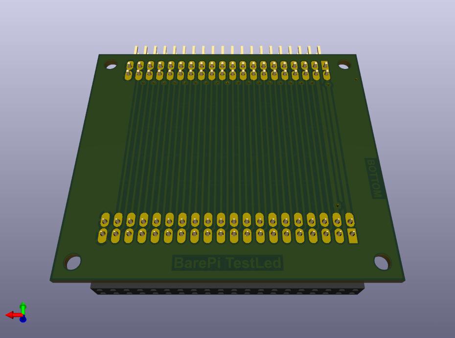
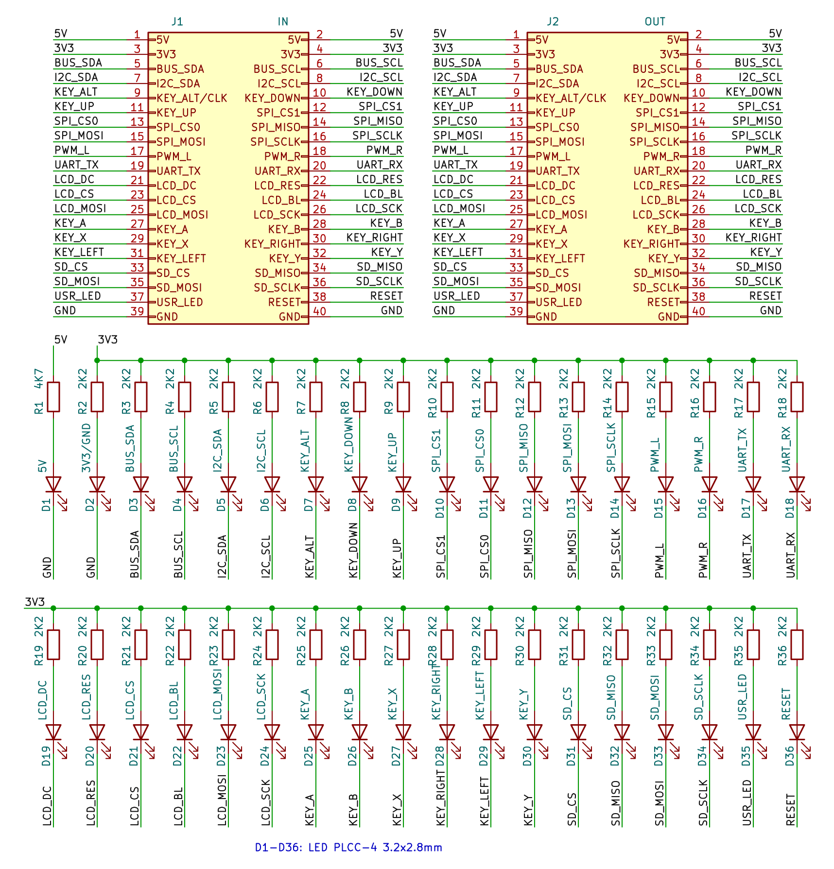
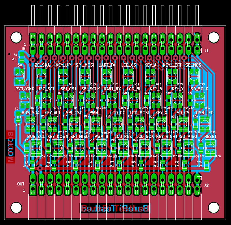
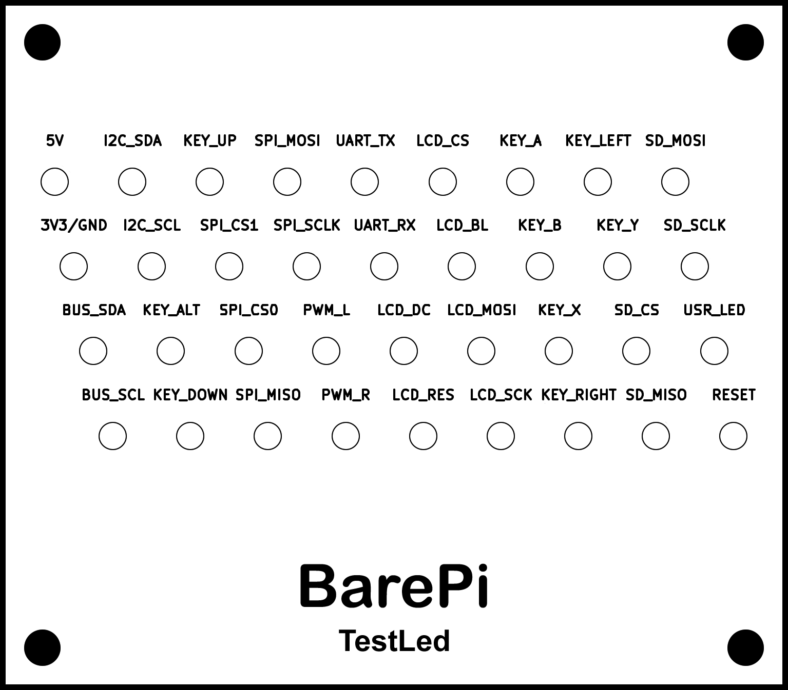
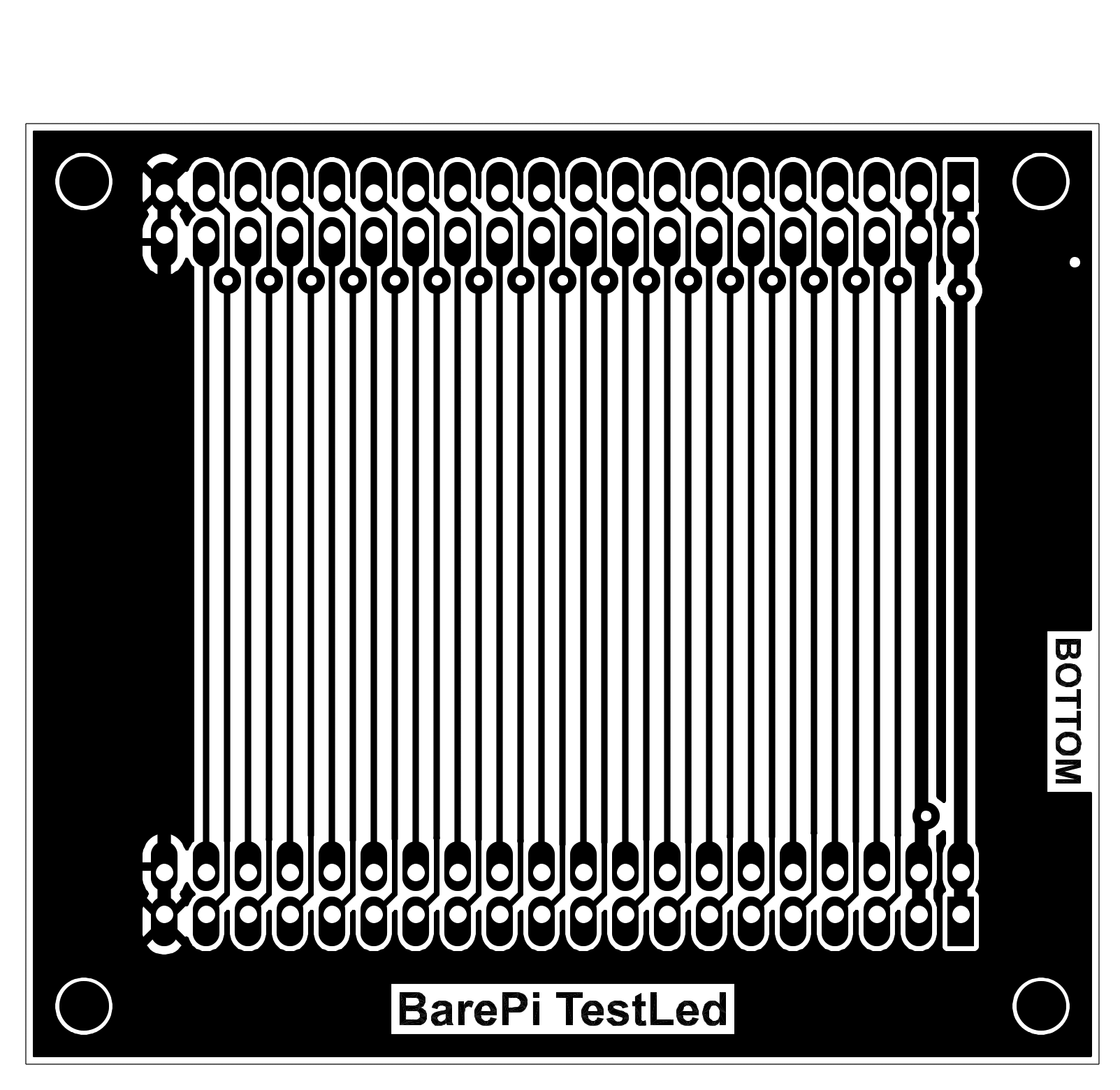
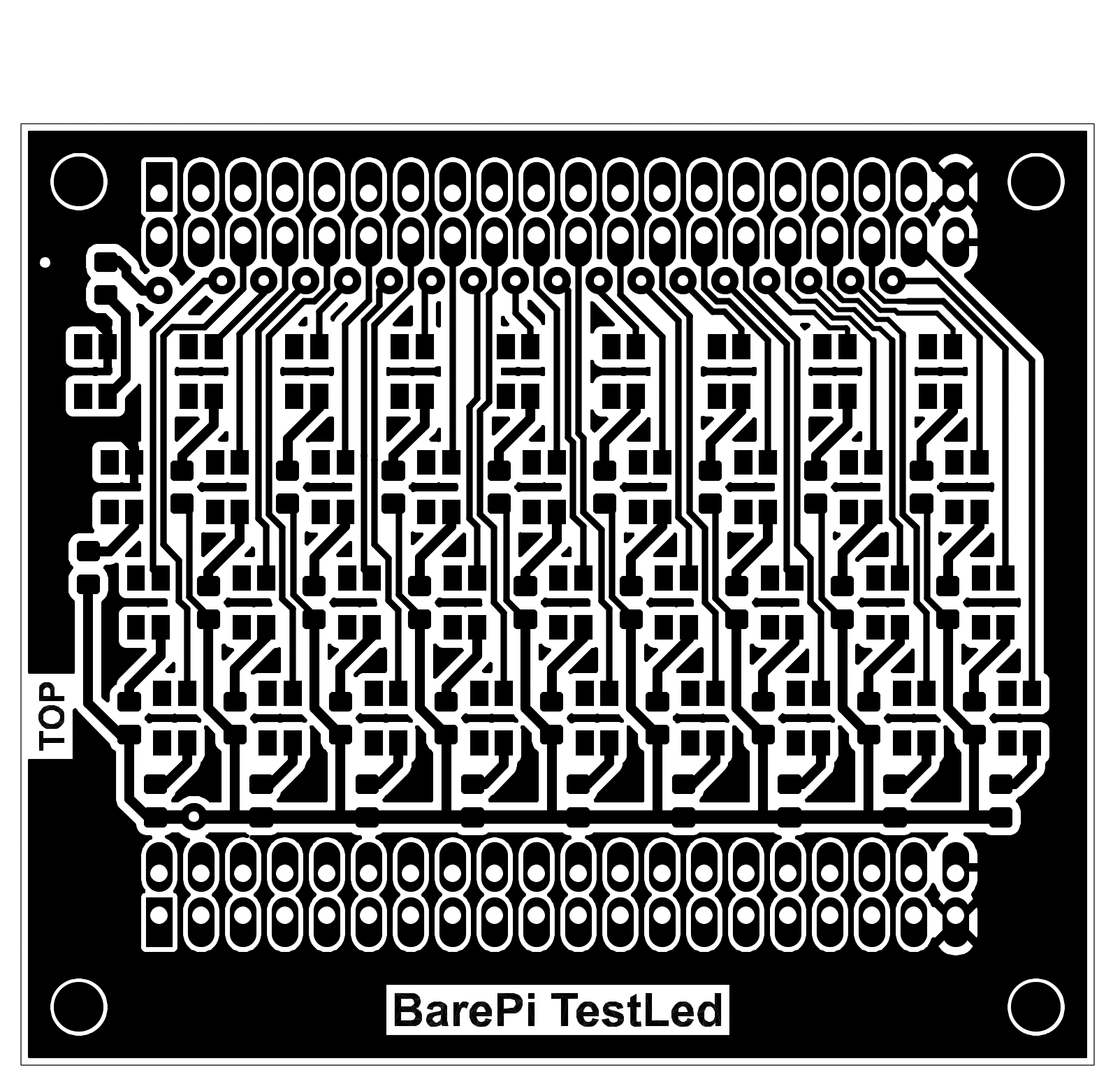
The "TestLed" module is a test module for testing the kit bus. It uses LEDs to indicate the states of the bus signals. Almost all LEDs, except for the LEDs for indicating the 5V and 3.3V supply voltages, are connected between the signal and the 3.3V supply voltage. By lighting up, they indicate the LOW state - because most signals are negative, when the idle state is HIGH and the active state is LOW. The exceptions are some signals, such as USR_LED, PWM_L, PWM_R, LCD_BL, which have a positive meaning and it might be more appropriate to indicate their level HIGH. But due to the possibility of easy detection of a short circuit between the signals, the same connection is left for these special cases of signals. The test LED for the USR_LED signal will therefore be on if the user LED is off, and similarly the LED for the display backlight will be on if the backlight is turned off. Of course, in cases where the signal is not used and is in a high impedance state, the LEDs will not light up even at the LOW level. For easy bus testing, a program can be loaded into some processors that gradually lights up the LEDs for bus signals, so you can visually check for bus interruption or short circuit errors on the bus. You can test the bus (except for the last 6 signals) using the "Zero" processor module and the TESTLED program from the PiLibSDK library, TEST folder: www GitHub.
The module uses SMD LEDs with PLCC-4 package. Different manufacturers use different pin connections - therefore, only 2 contacts out of 4 are used on the printed circuit board, the connection of which is followed by manufacturers.
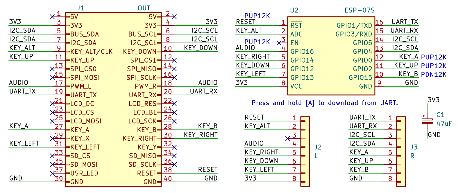
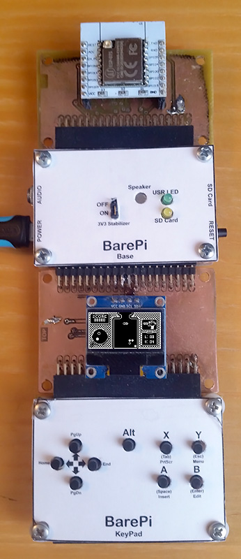
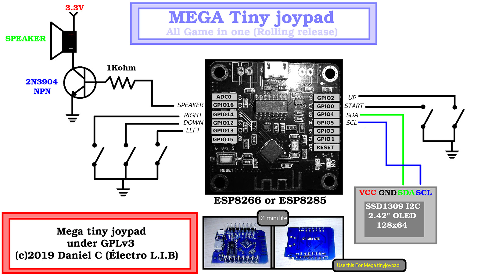
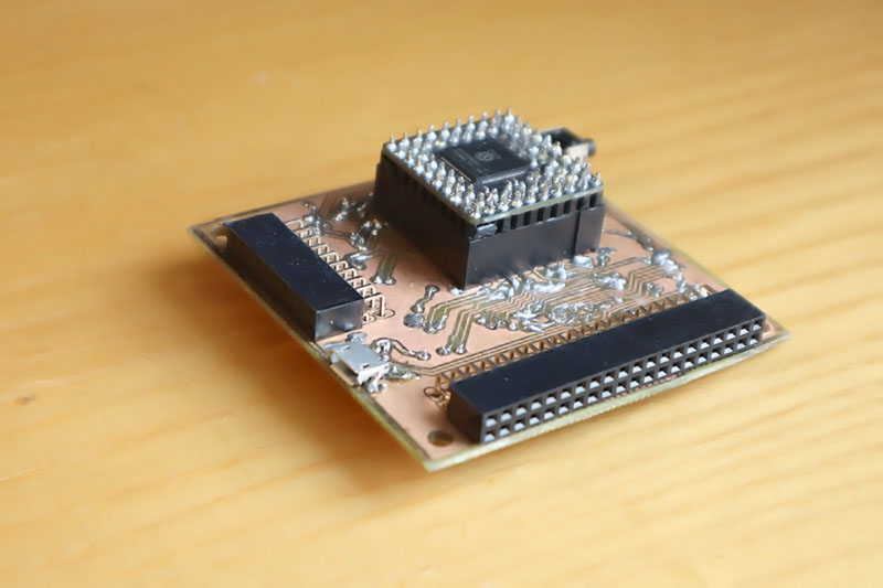
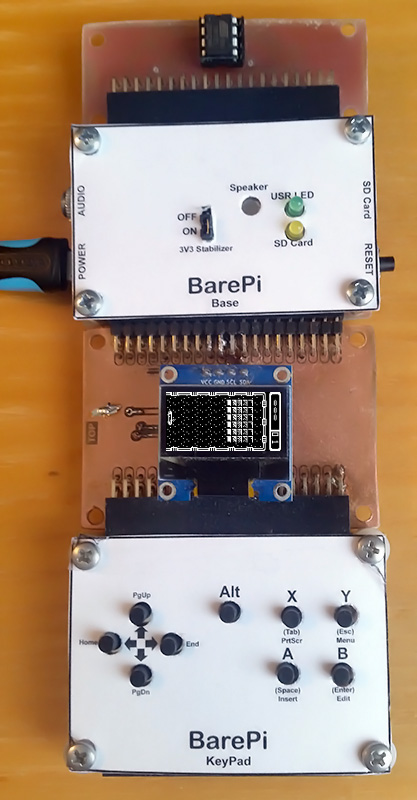
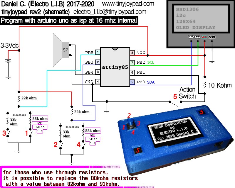
The "MegaTinyJoypad" module is designed to control the "MEGA Tiny Joypad" game console, designed by (c) Daniel C (Electro L.I.B). The module contains an ESP-07S processor unit, which can either be soldered to the module directly, or use an adapter for ESP-07 and a connector with a female connector strip. The program can be uploaded to the processor via UART pins, after pressing the "A" button during power-on. The "Base", "OLED128x64" and "KeyPad" modules need to be connected to the module.
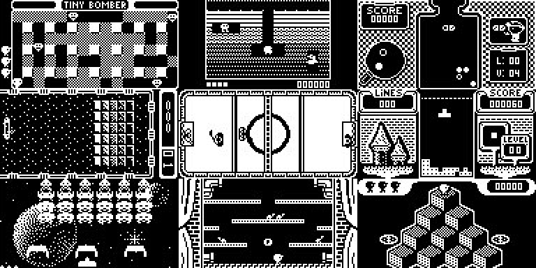
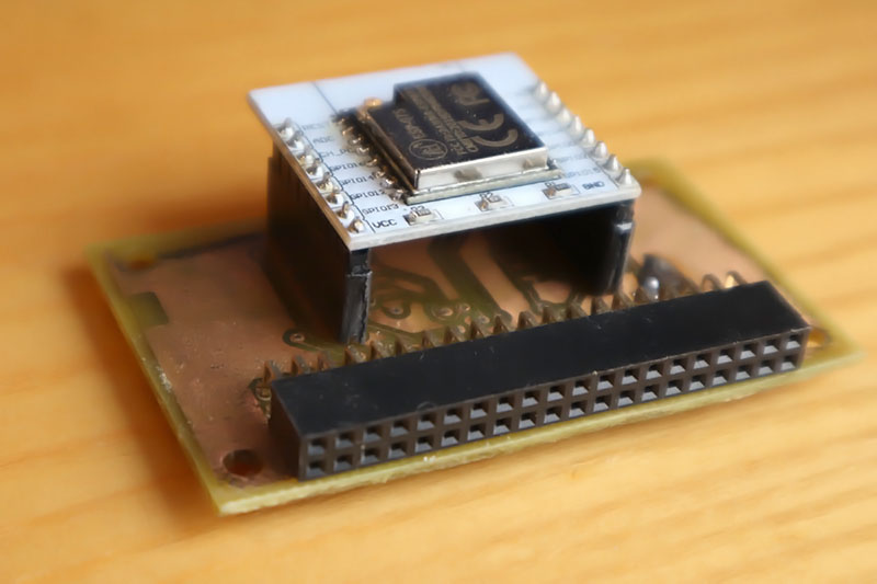
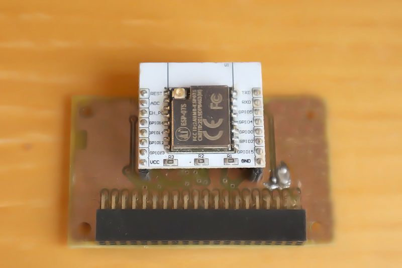
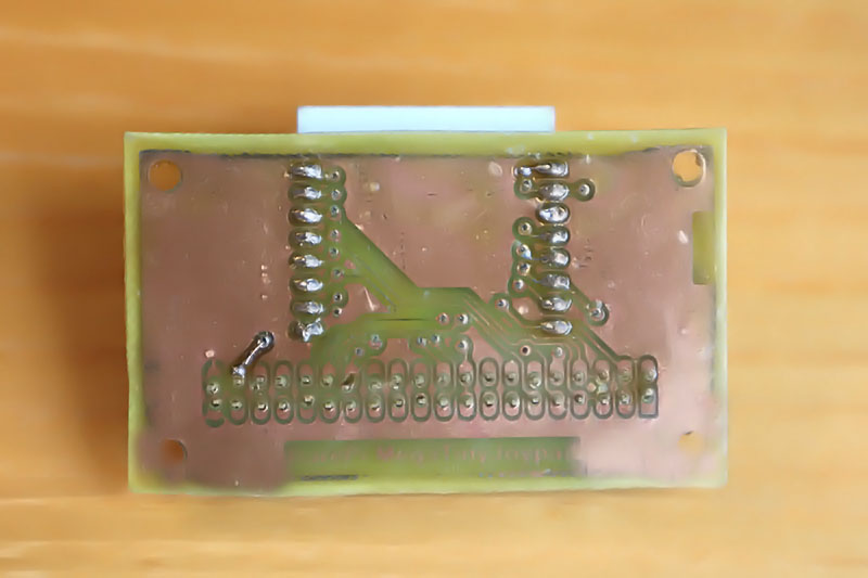
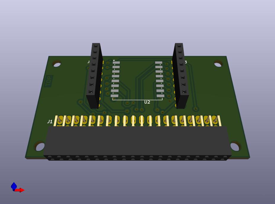
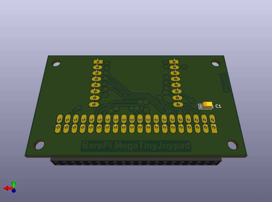
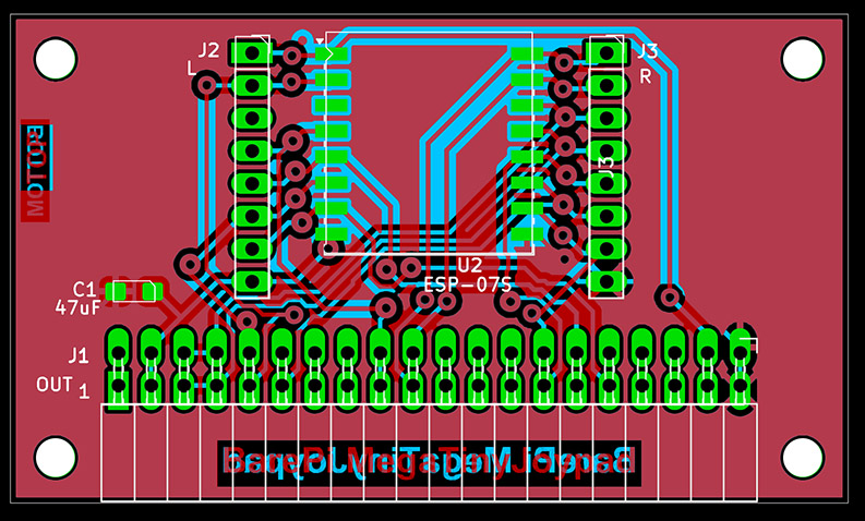
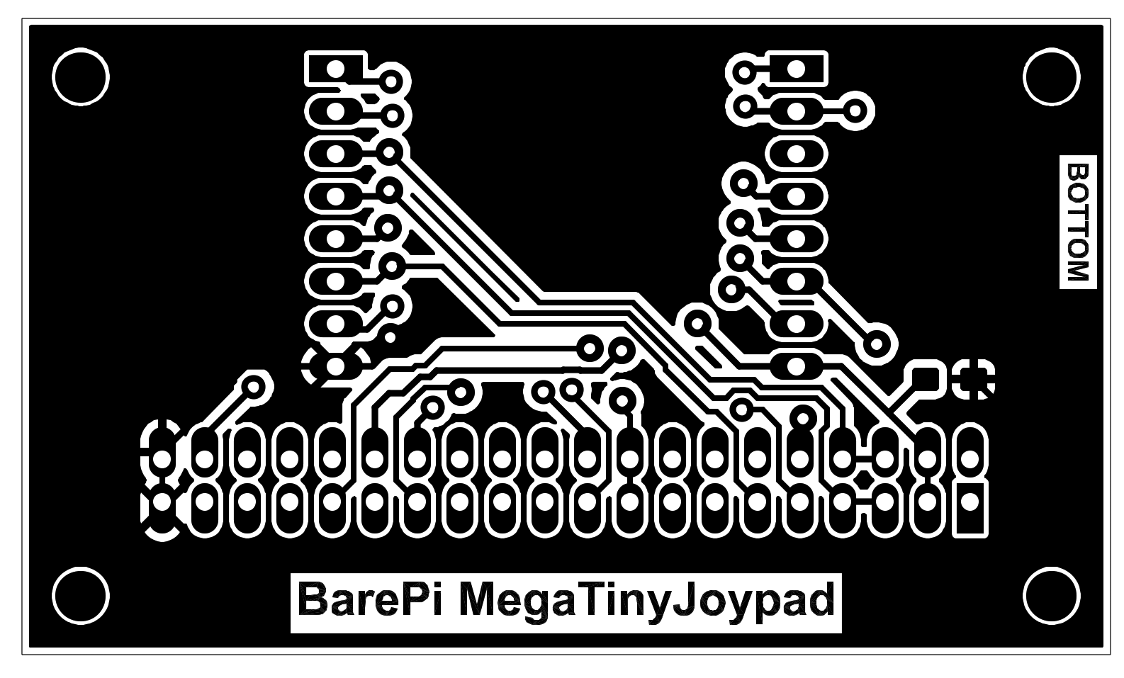
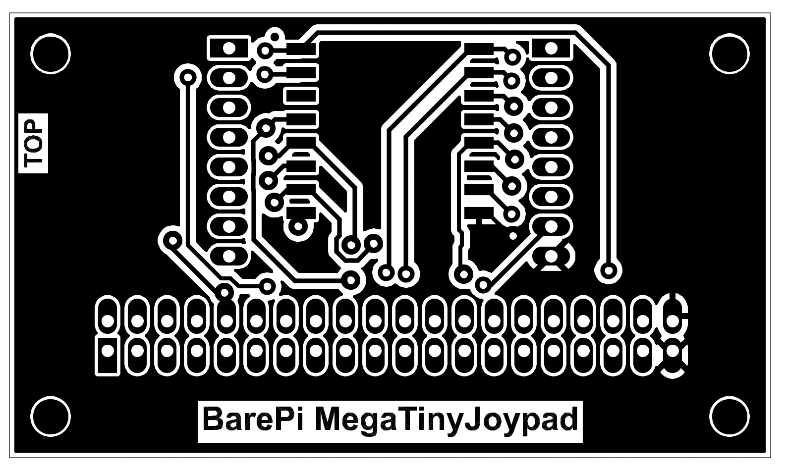
Mega Tiny Joypad console built from BarePi modules:
Mega Tiny Joypad console wiring diagram:
The "PGA2350" module is used to build the PicoPadPGA game console. It is a variant of the PicoPad console featuring the PGA2350 processor module, which includes an RP2350B processor, 16 MB of Flash memory, and 8 MB of PSRAM. Video output is supported for a 320x240-pixel LCD display, a VGA monitor, or an HDMI monitor. The module requires the connection of the "DispVGA", "DispHDMI", "LCD320x240", "Base" and "KeyPad" modules. The PicoPadPGA console software is based on the PicoLibSDK library (links: www, GitHub), but the software for the PicoPadPGA console is not yet ready.
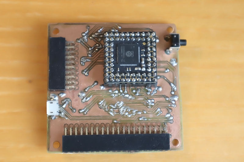
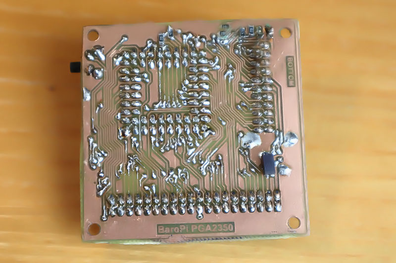
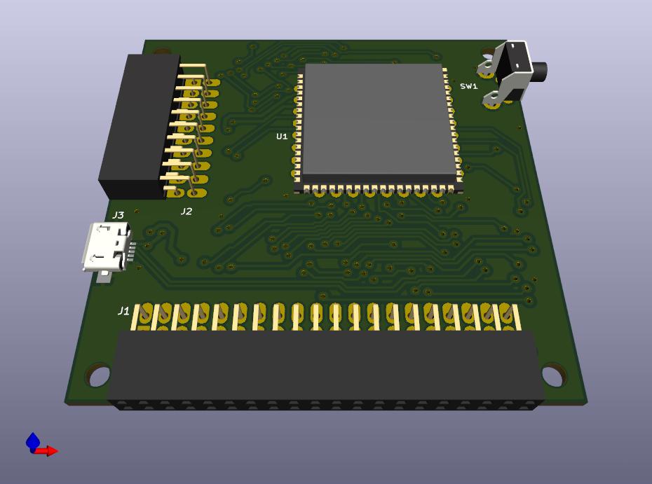
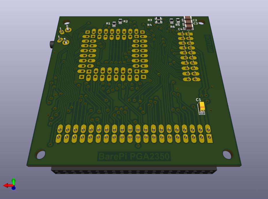
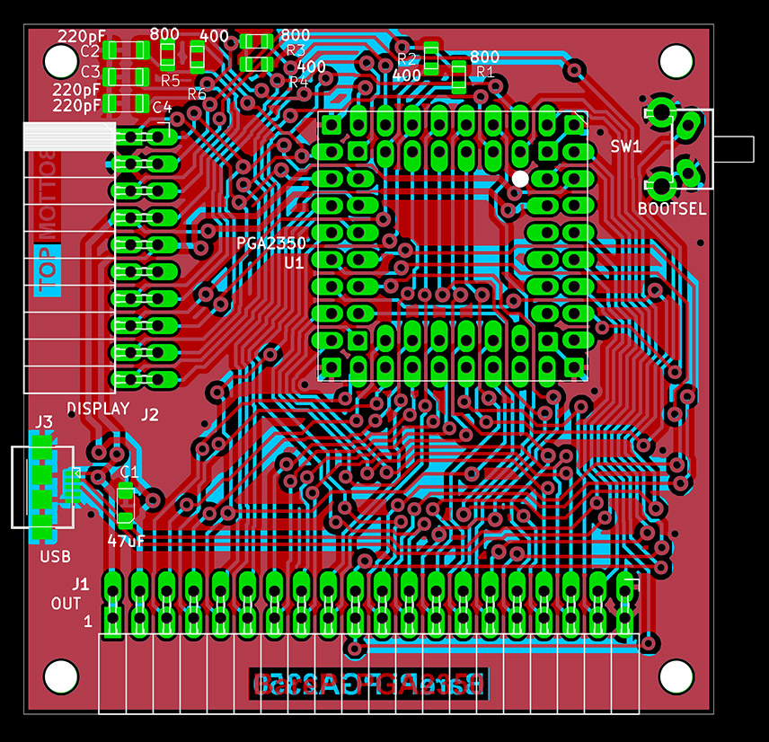
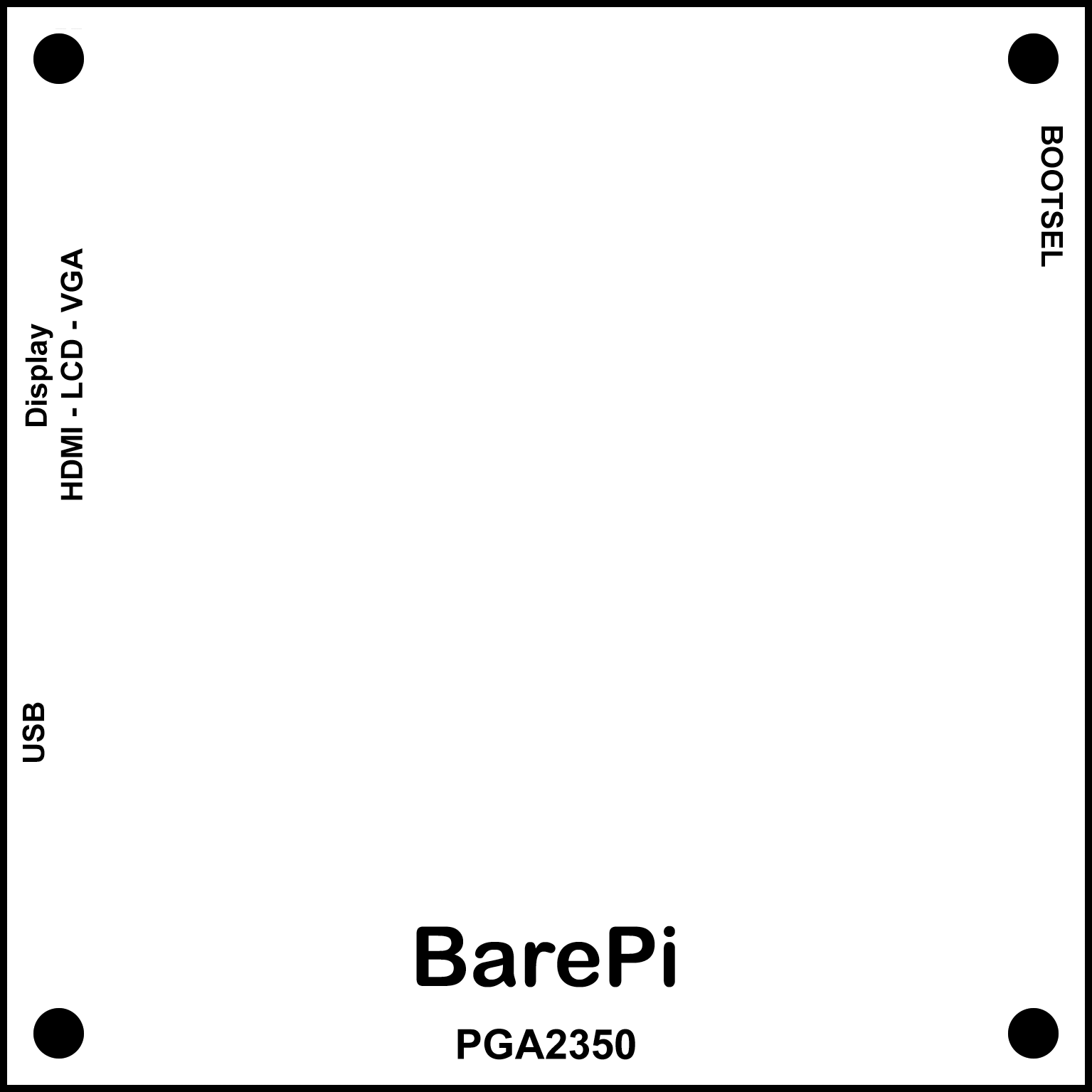
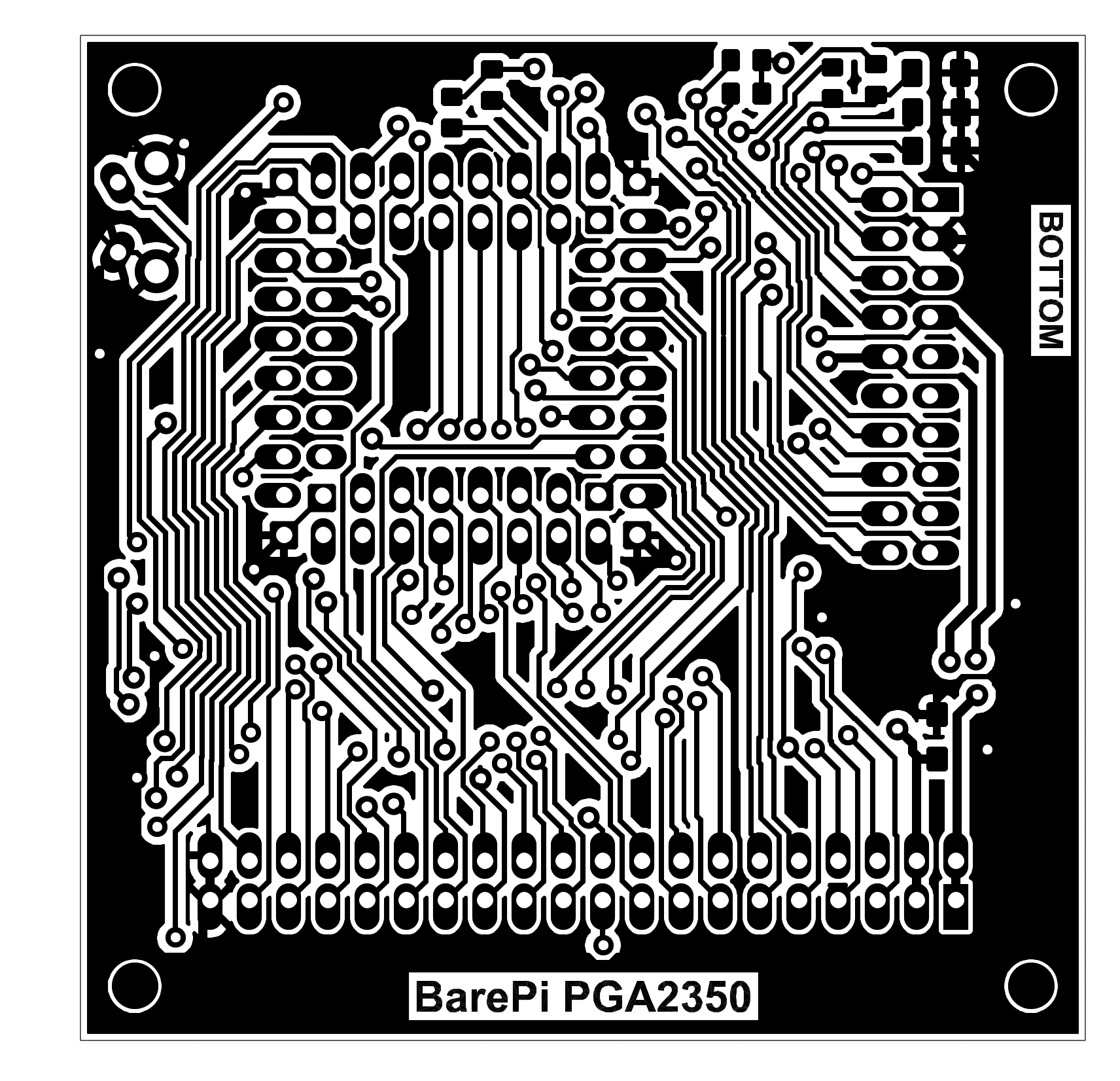
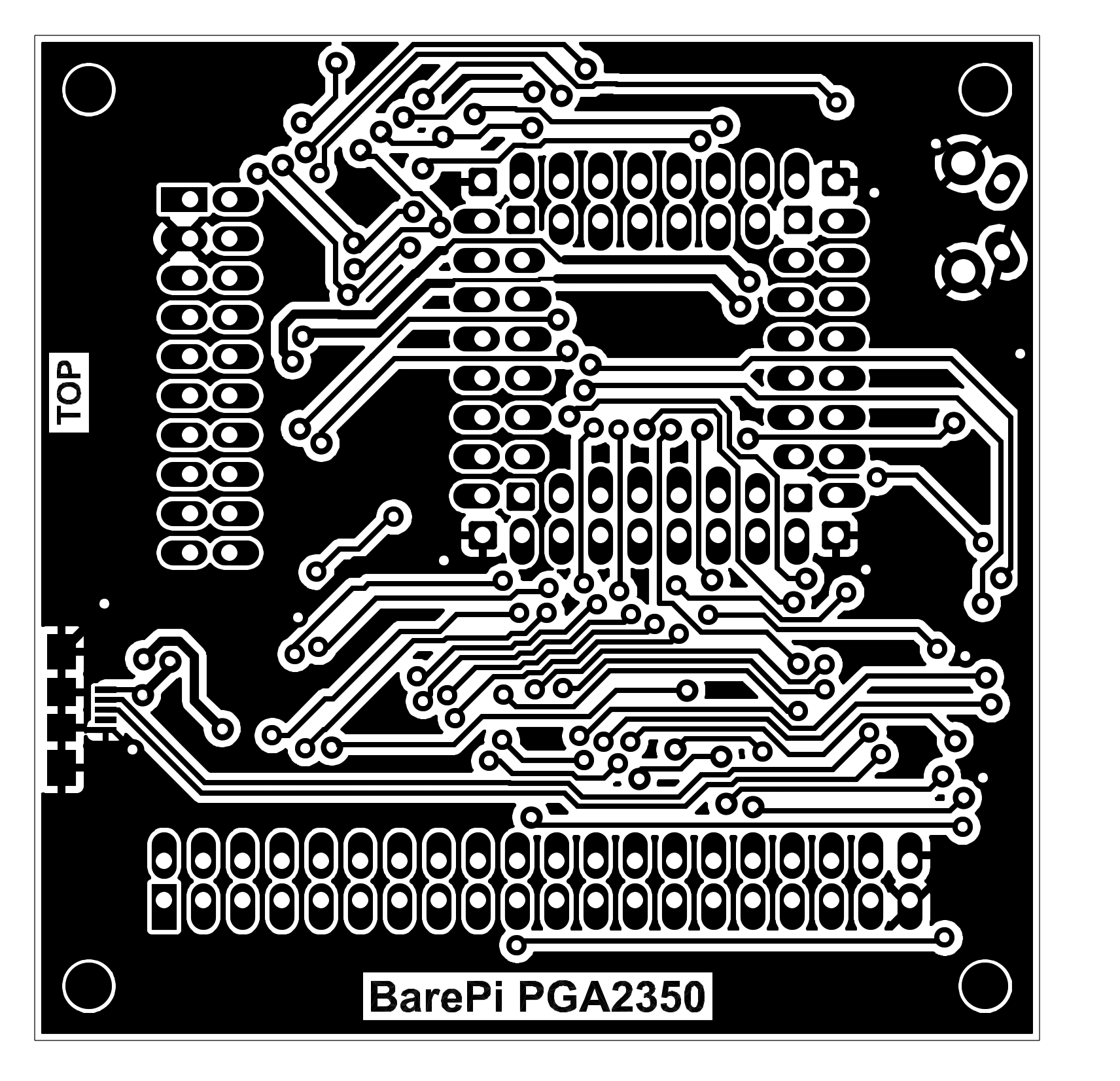
PicoPadPGA console built from BarePi modules:
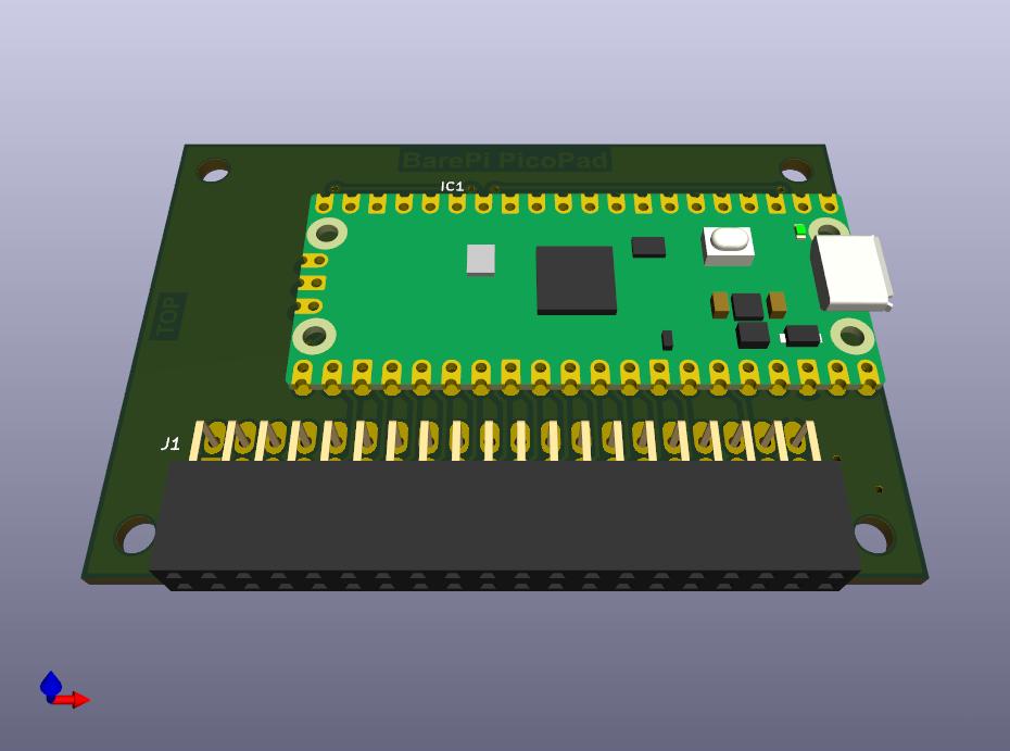
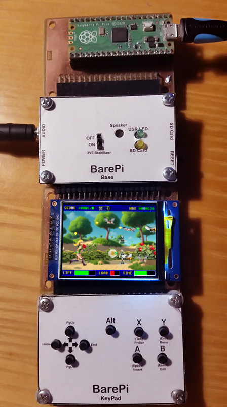
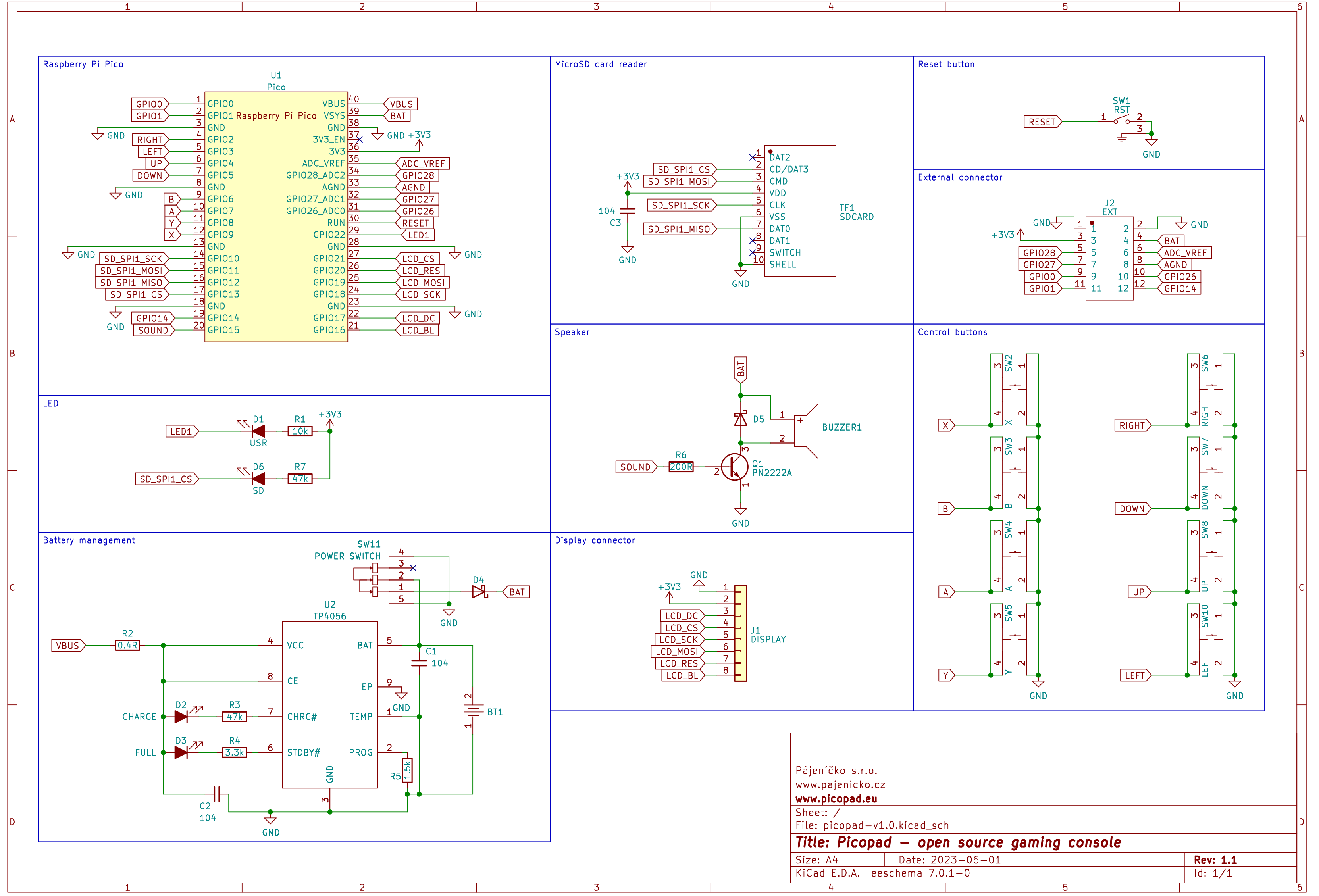
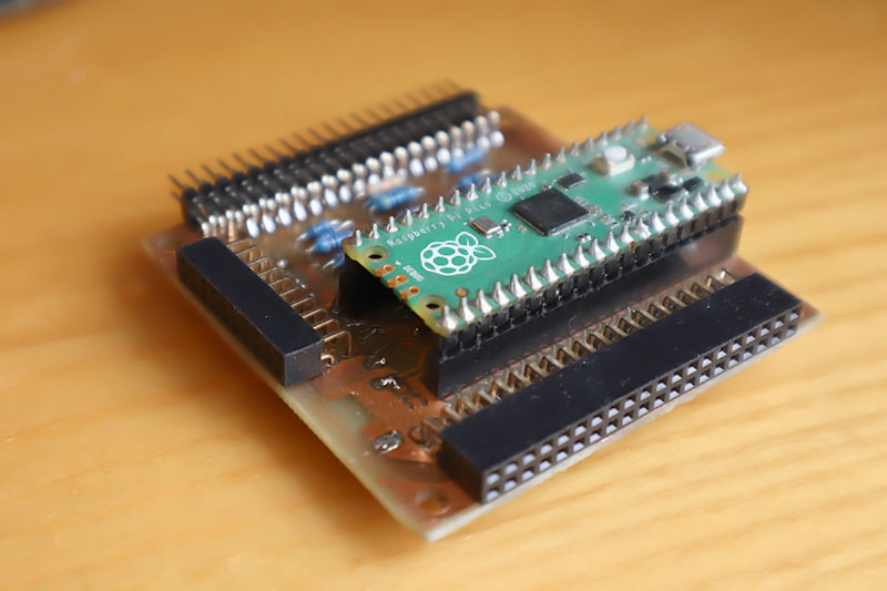
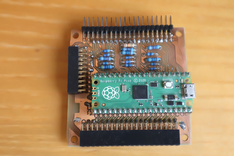
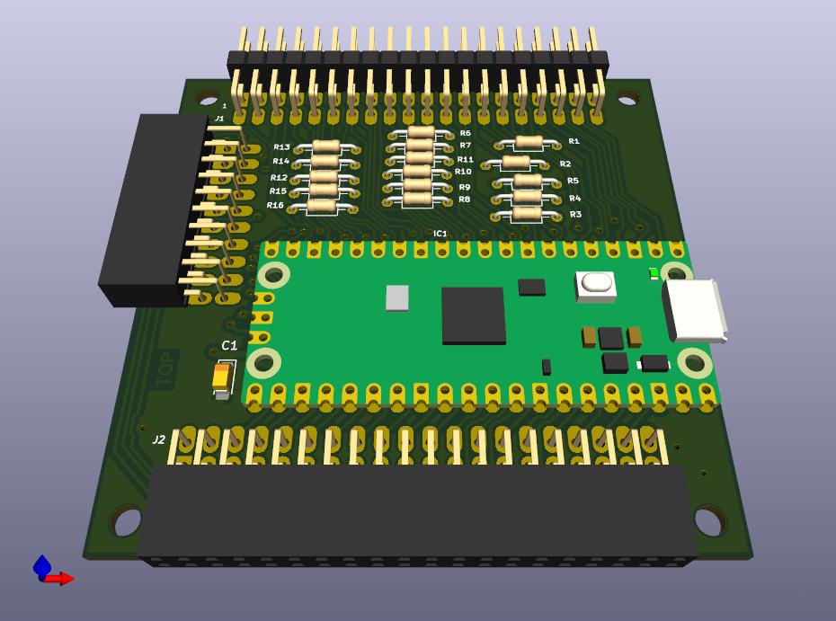
The "PicoPad" module is used to assemble the PicoPad game console. I recommend not soldering the Pico module to the module, but using female connectors to allow easy exchange between the Pico 1, Pico 2 (PicoPad 2) and Pimoroni Pico Plus 2 modules. The "Base", "LCD320x240" and "KeyPad" modules need to be connected to the module. The PicoPad console in the PicoLibSDK library, where you can also find sample applications: www, GitHub.
The original PicoPad console uses mono audio on the GPIO14 port. In the "PicoPad" module, the original audio from GPIO14 is routed to PWM_L, so you will hear audio from standard programs in the left channel. The GPIO15 port can be used for the right channel of stereo audio. However, it is necessary to modify the PicoPad programs for this option. To play MP3 music, you can use the MP3_1514 program, which has already been modified to play audio through the GPIO15/GPIO14 ports.

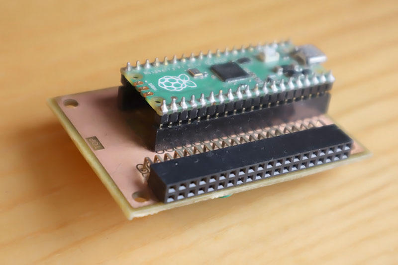
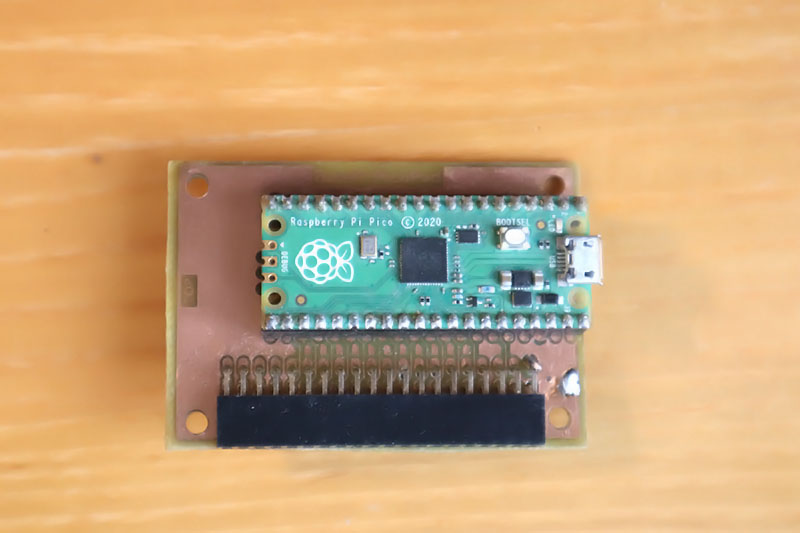
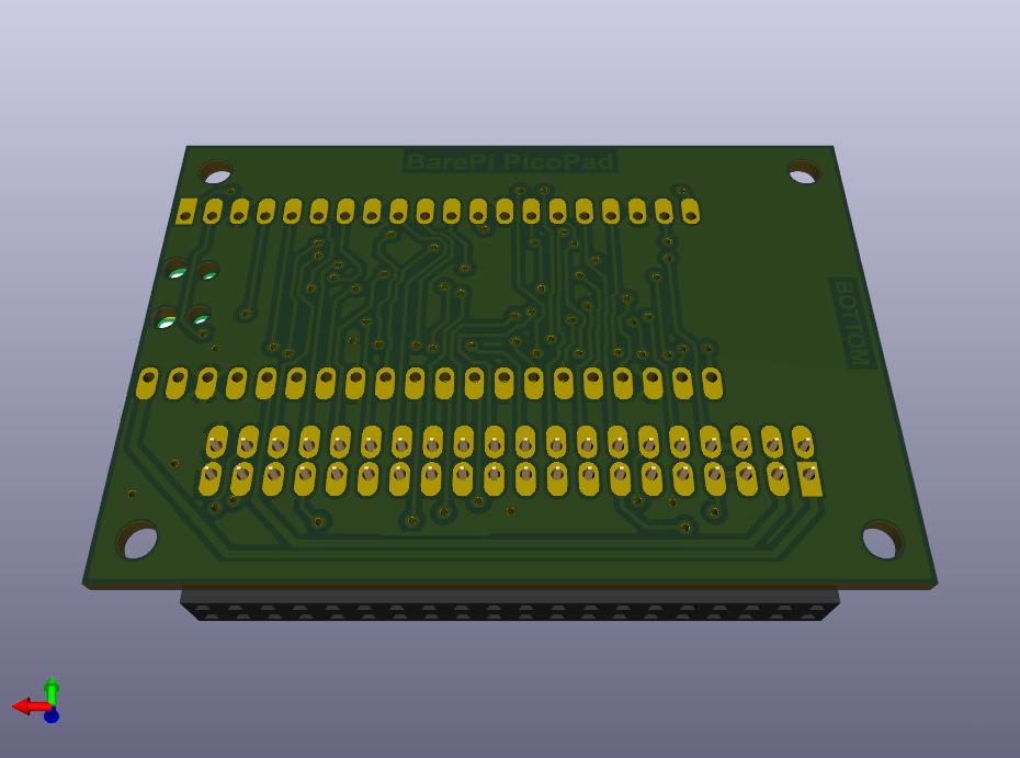
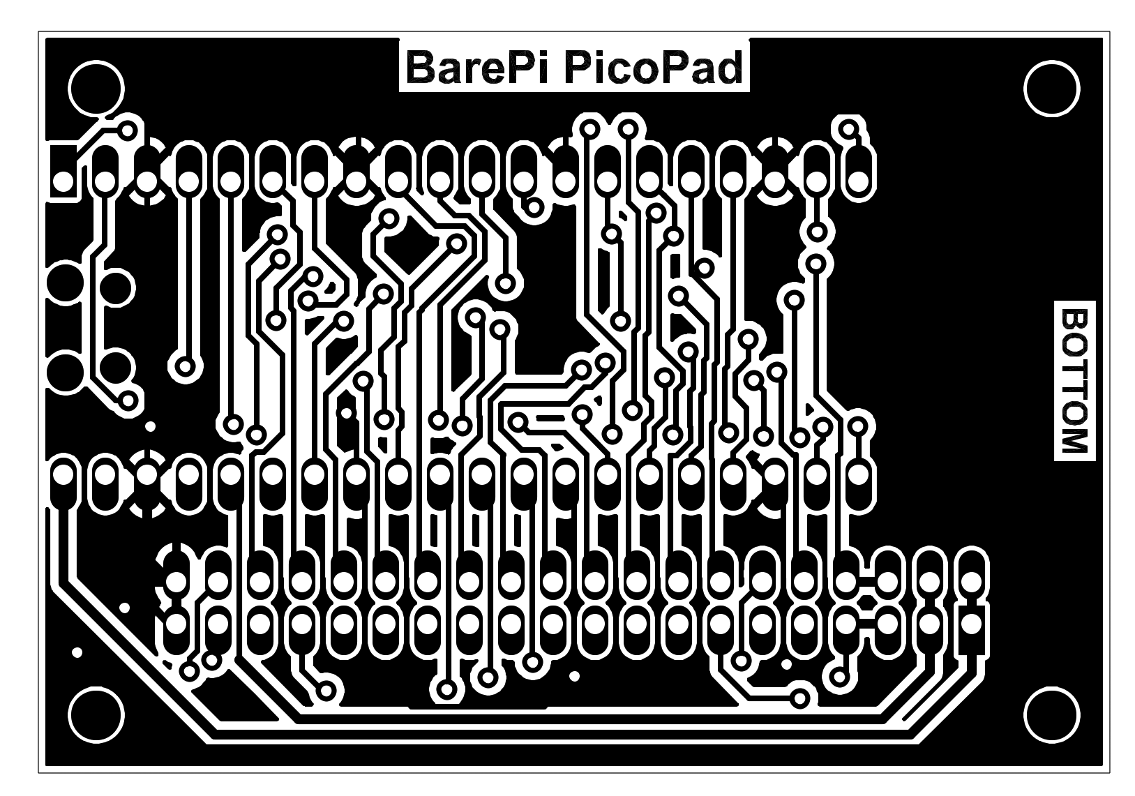
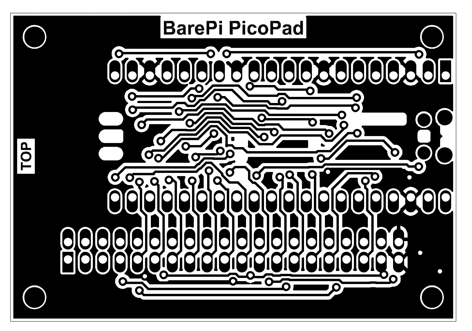
PicoPad console built from BarePi modules:
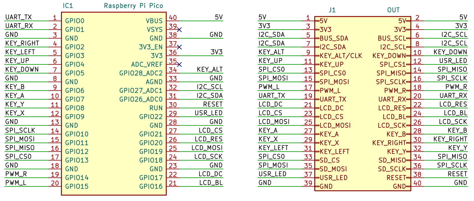
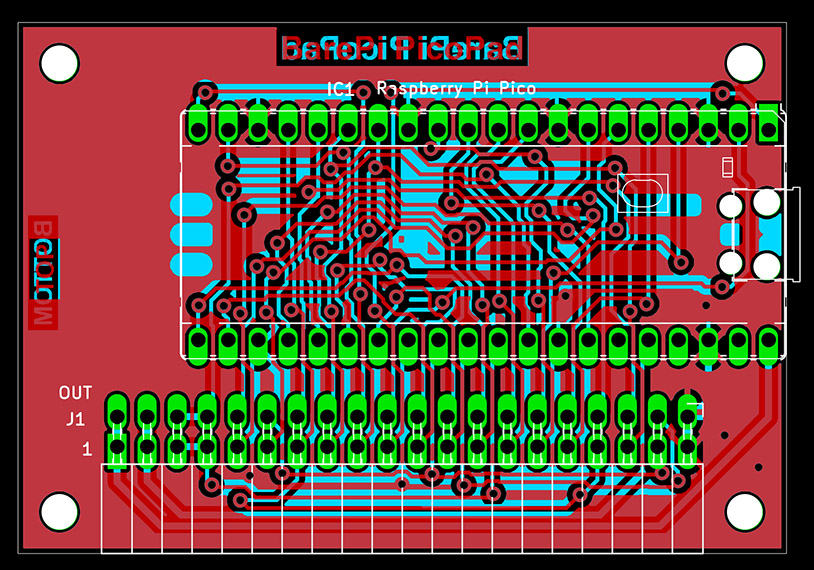
PicoPad console wiring diagram:
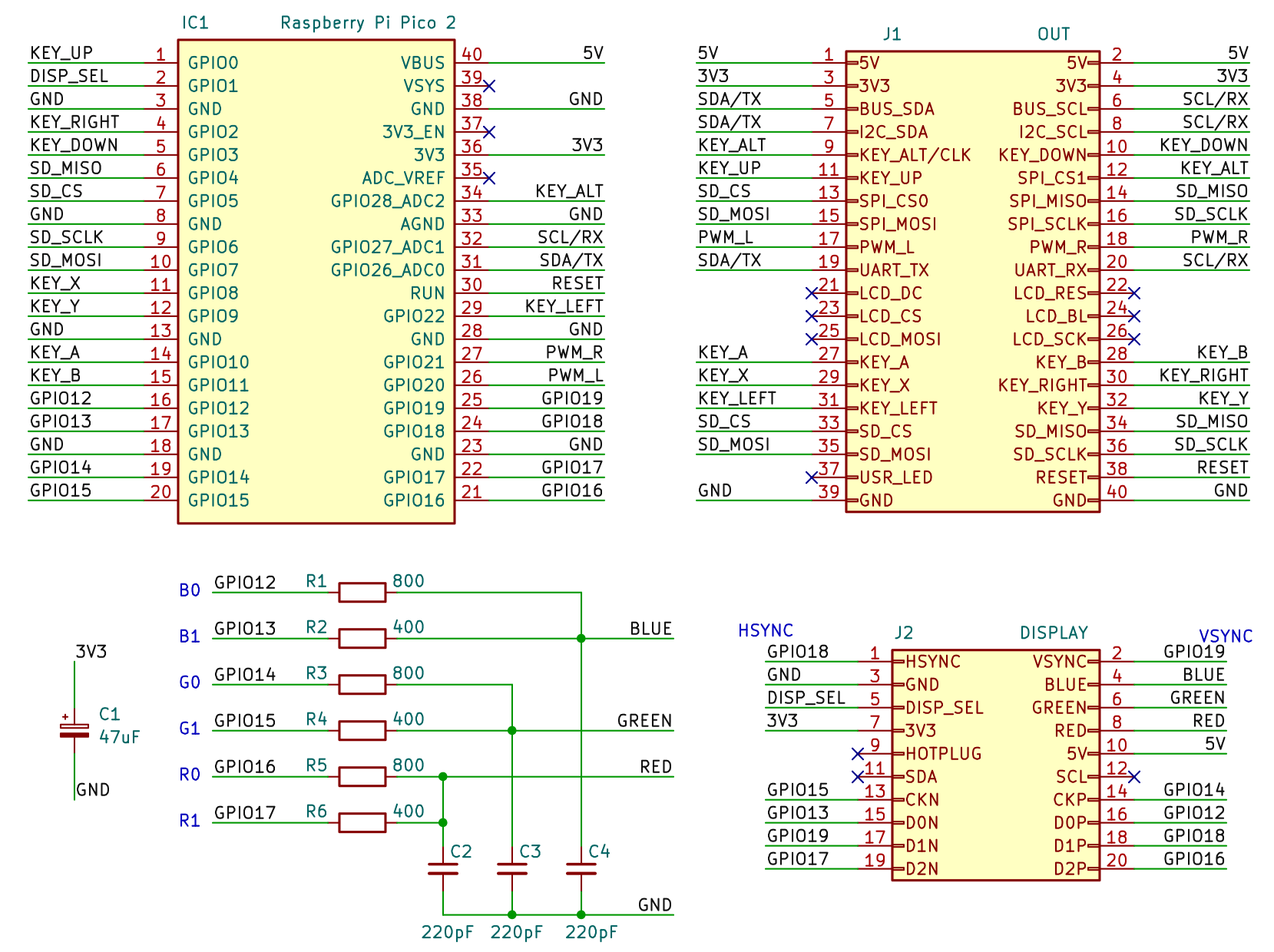
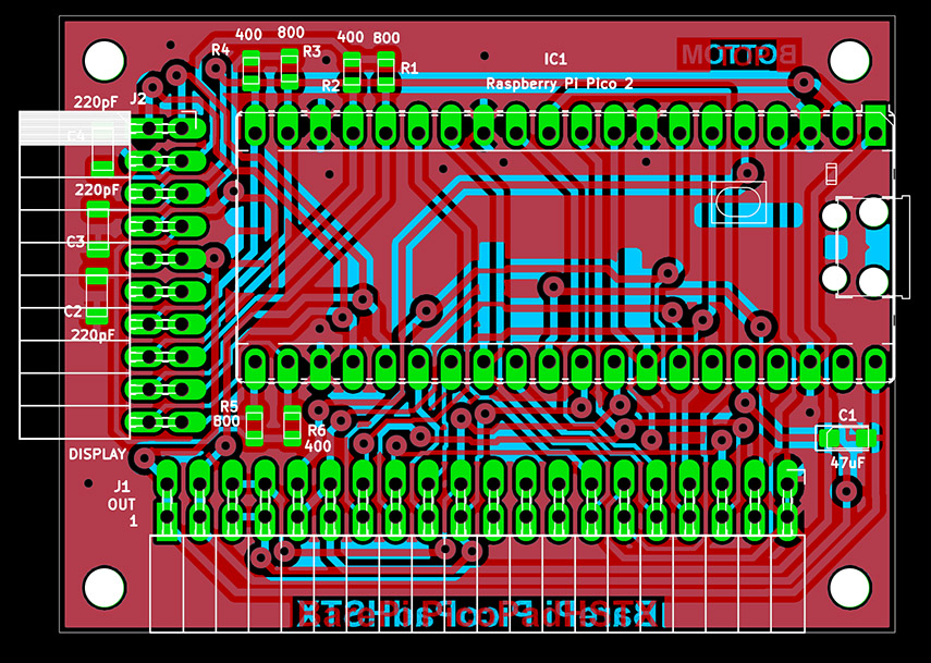
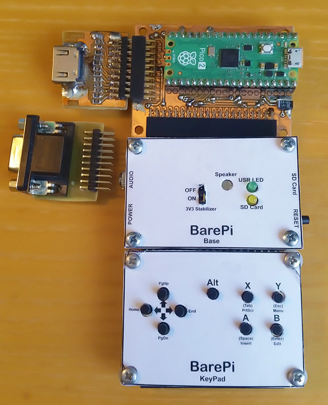
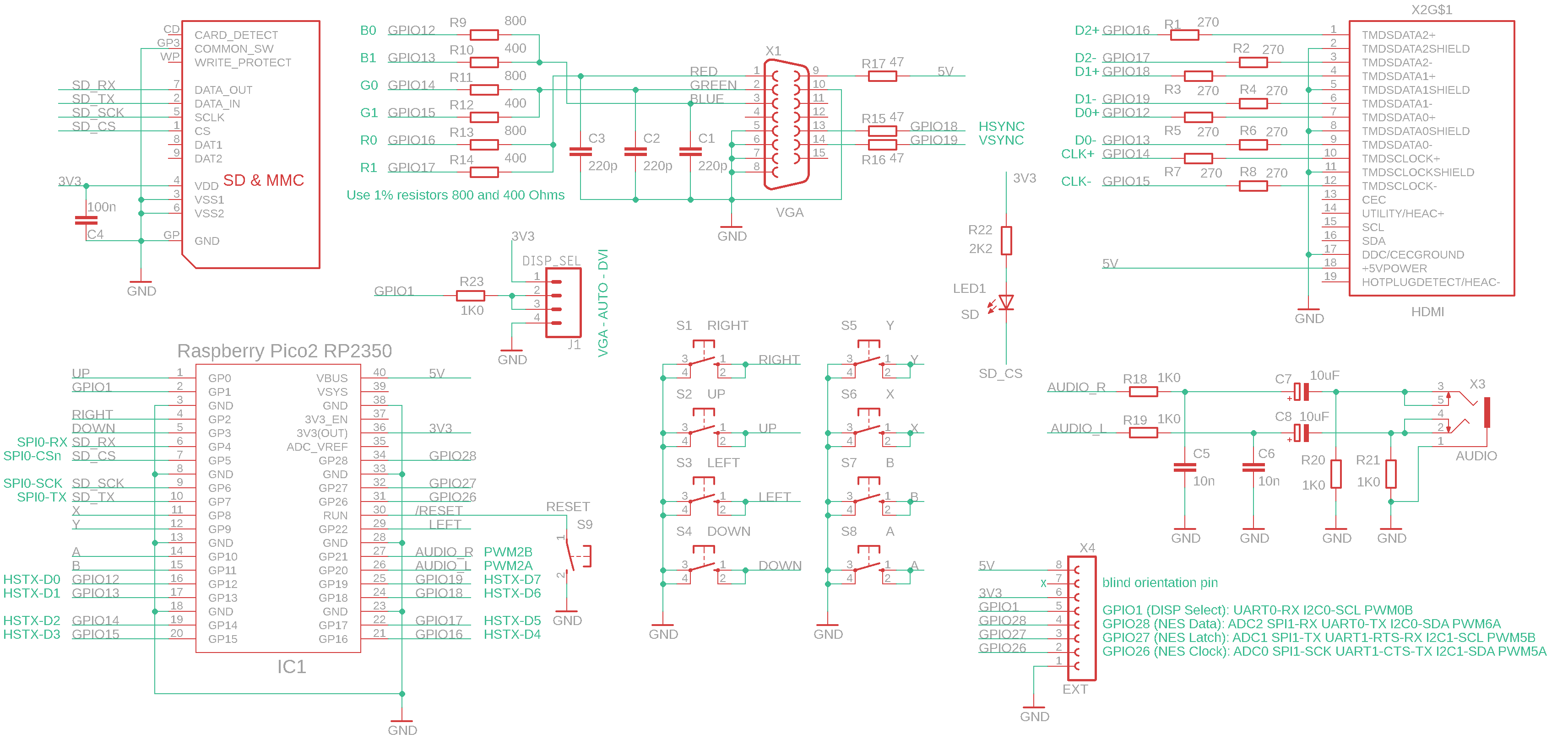
The "PicoPadHSTX" module is used to assemble the PicoPadHSTX game console, which is equipped with a "Pico 2" or "Pimoroni Pico Plus 2" module. The "DispVGA", "DispHDMI", "Base" and "KeyPad" modules must be connected to this module. There may be noticeable increased noise in the audio due to the increased load on the internal voltage regulator caused by image generation. Modules with a higher-rated regulator (such as the Pimoroni Pico Plus 2) produce less noise. To reduce noise, I recommend leaving the regulator in the "Base" module active, which will boost the internal regulator of the Pico 2 module. Another option is to use an active PWM filter with a filtered supply voltage. The PicoPadHSTX console in the PicoLibSDK library, where you can also find sample applications: www, GitHub.
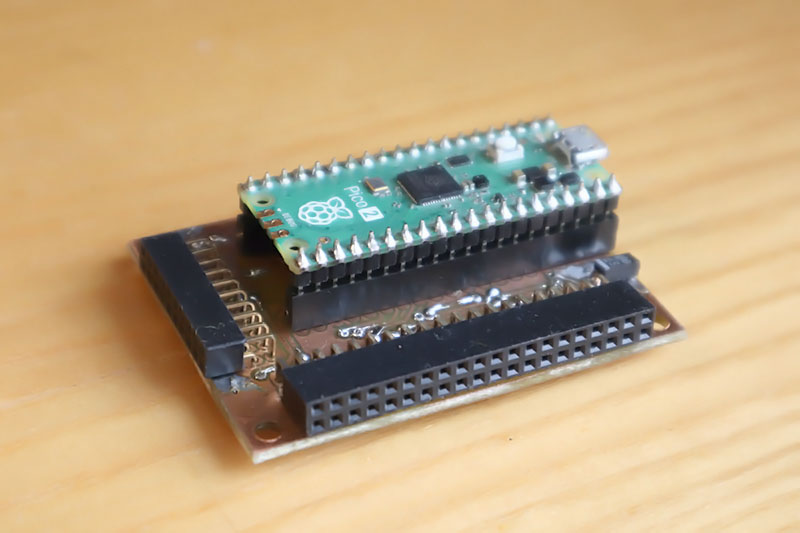
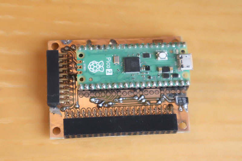
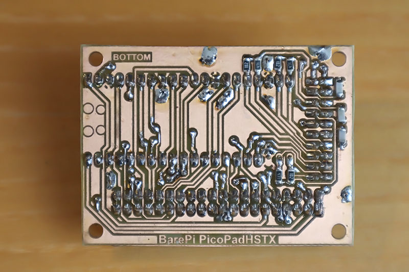
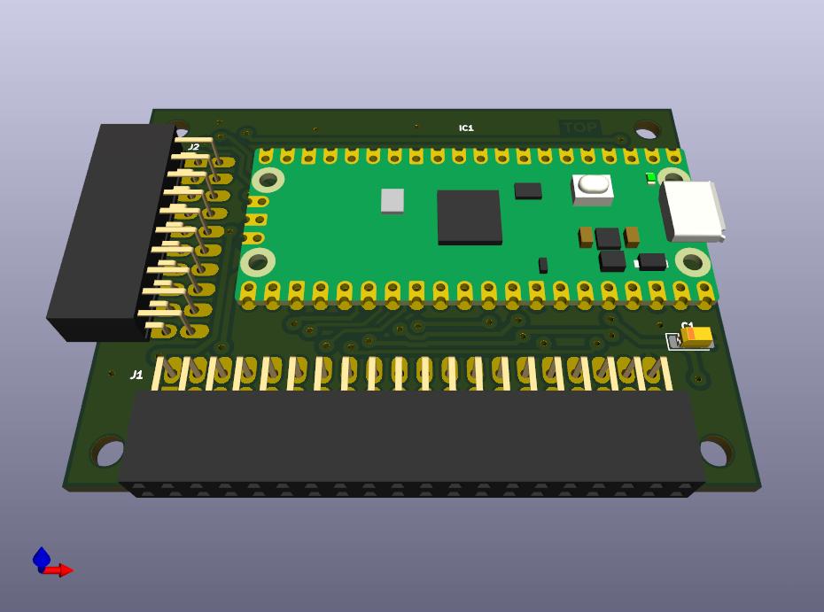
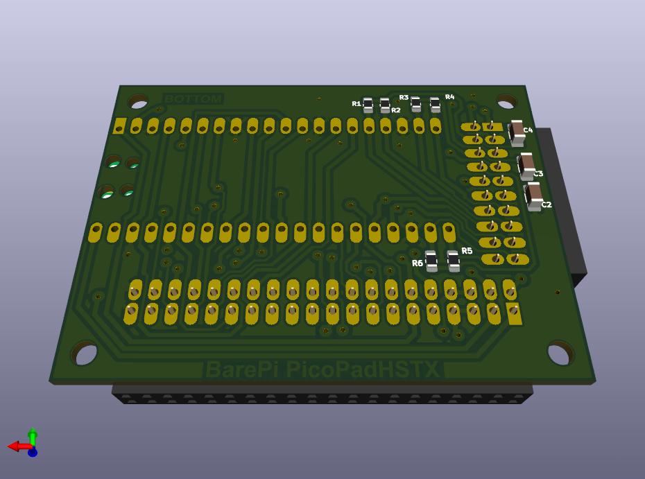
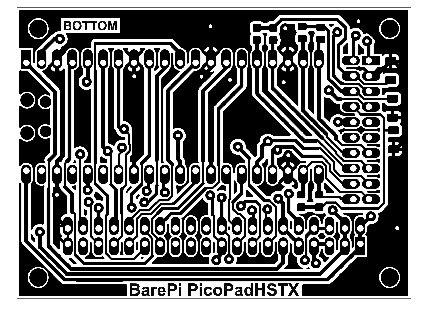
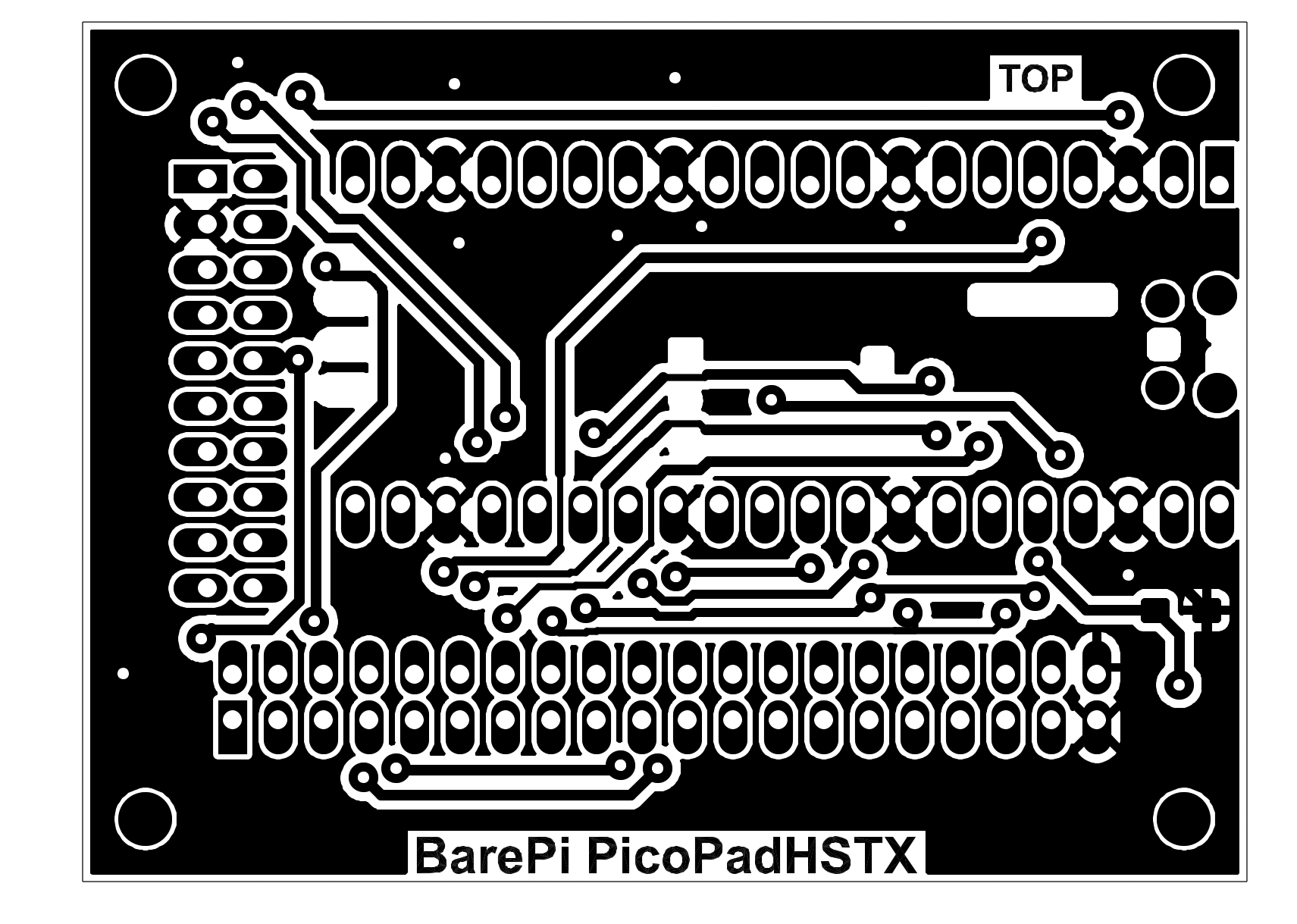
PicoPadHSTX console built from BarePi modules:
PicoPadHSTX console wiring diagram:
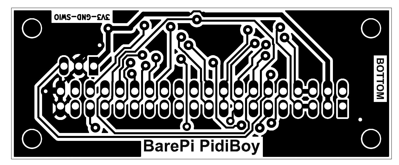
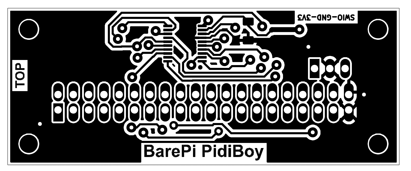
The "PidiBoy" module is designed to build a PidiBoy game console, with a CH32V006F8P6 processor and output to a 128x64 OLED display. The "Base", "OLED128x64" and "KeyPad" modules need to be connected to the module. The PidiBoy console in the CH32LibSDK library, where you can also find sample applications: www, GitHub.
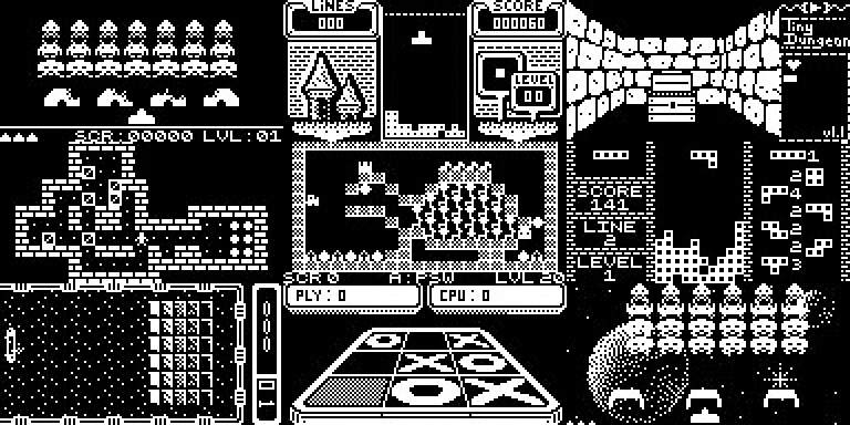
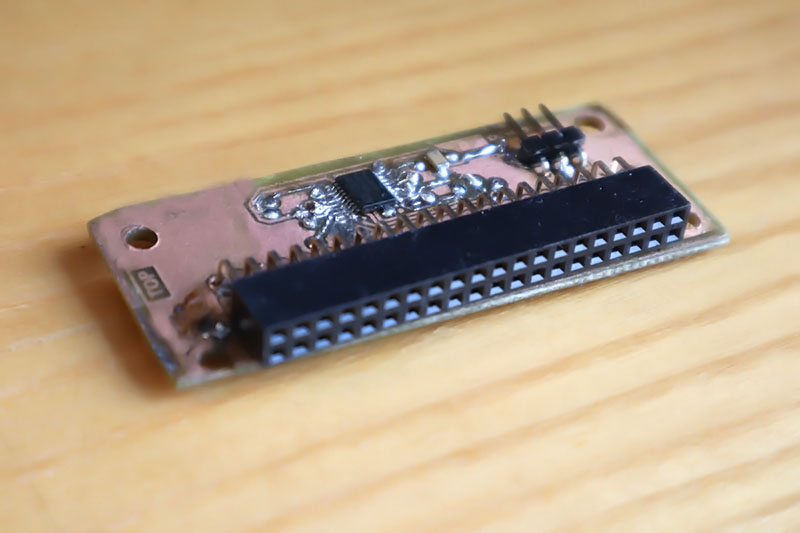
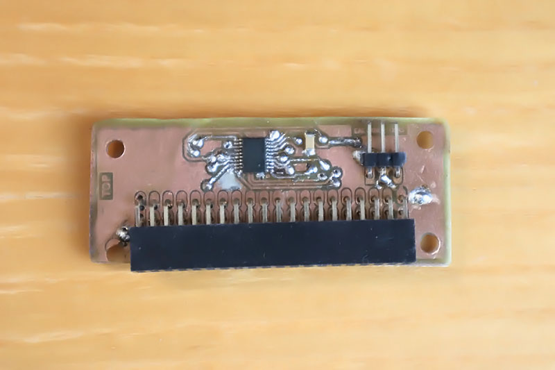
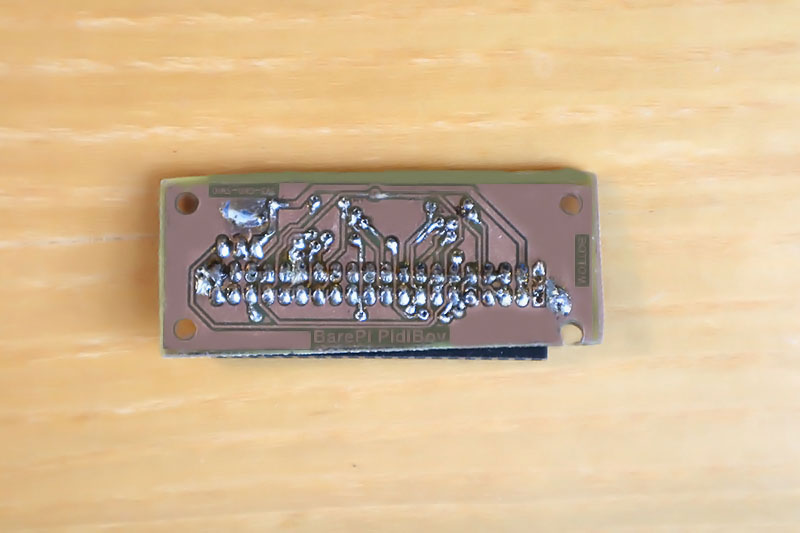
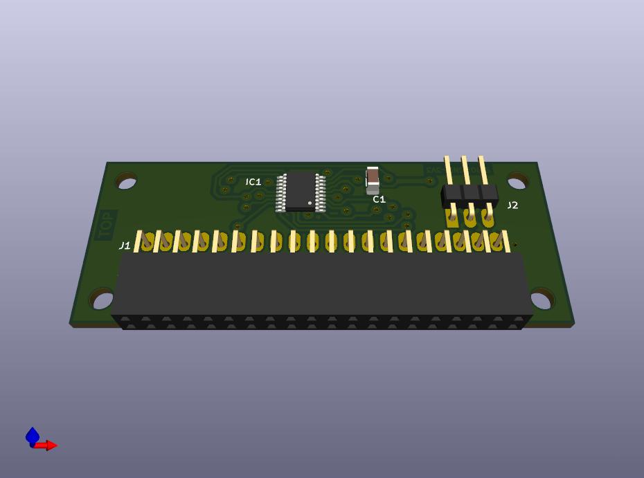
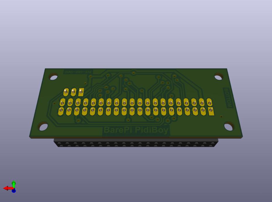
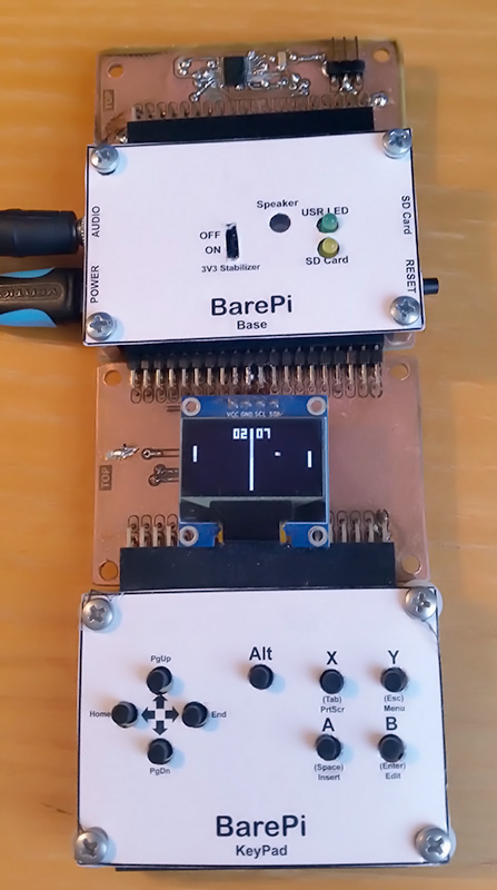
PidiBoy console built from BarePi modules:
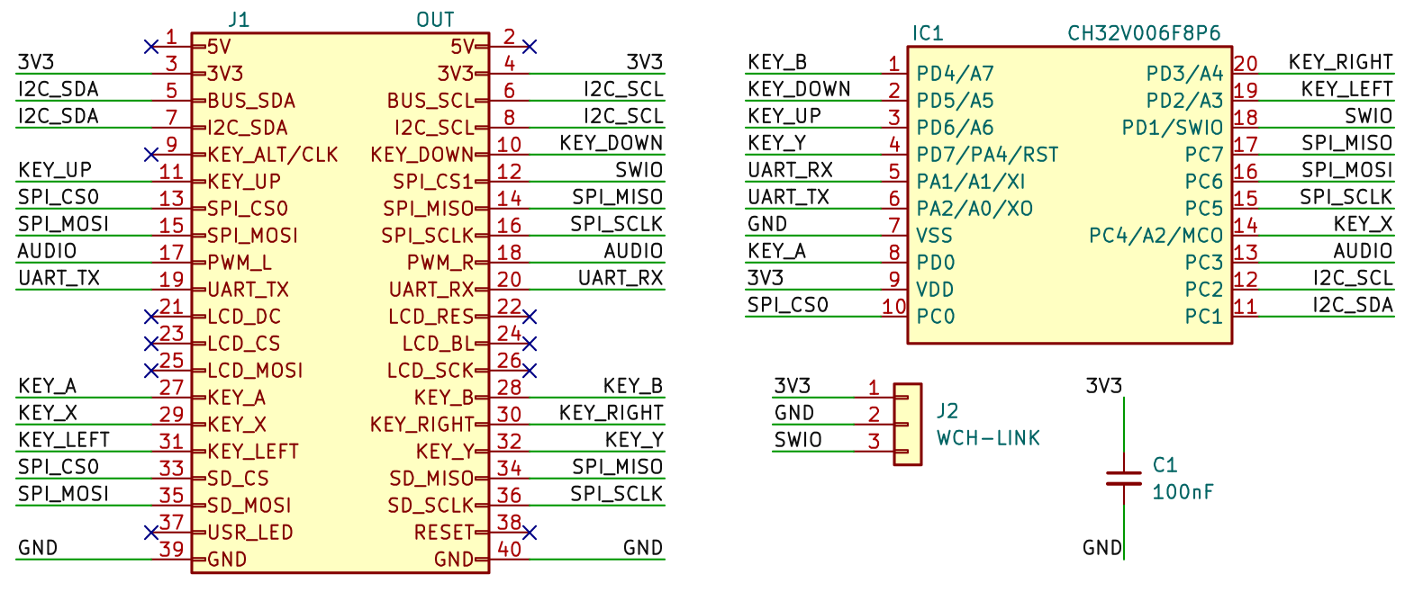
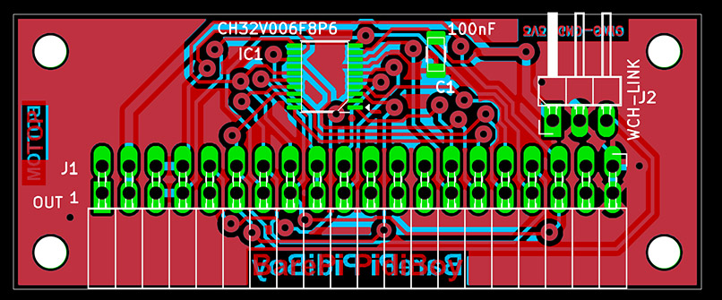
PidiBoy console wiring diagram:
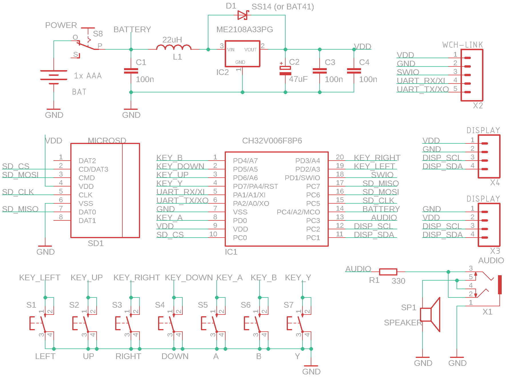
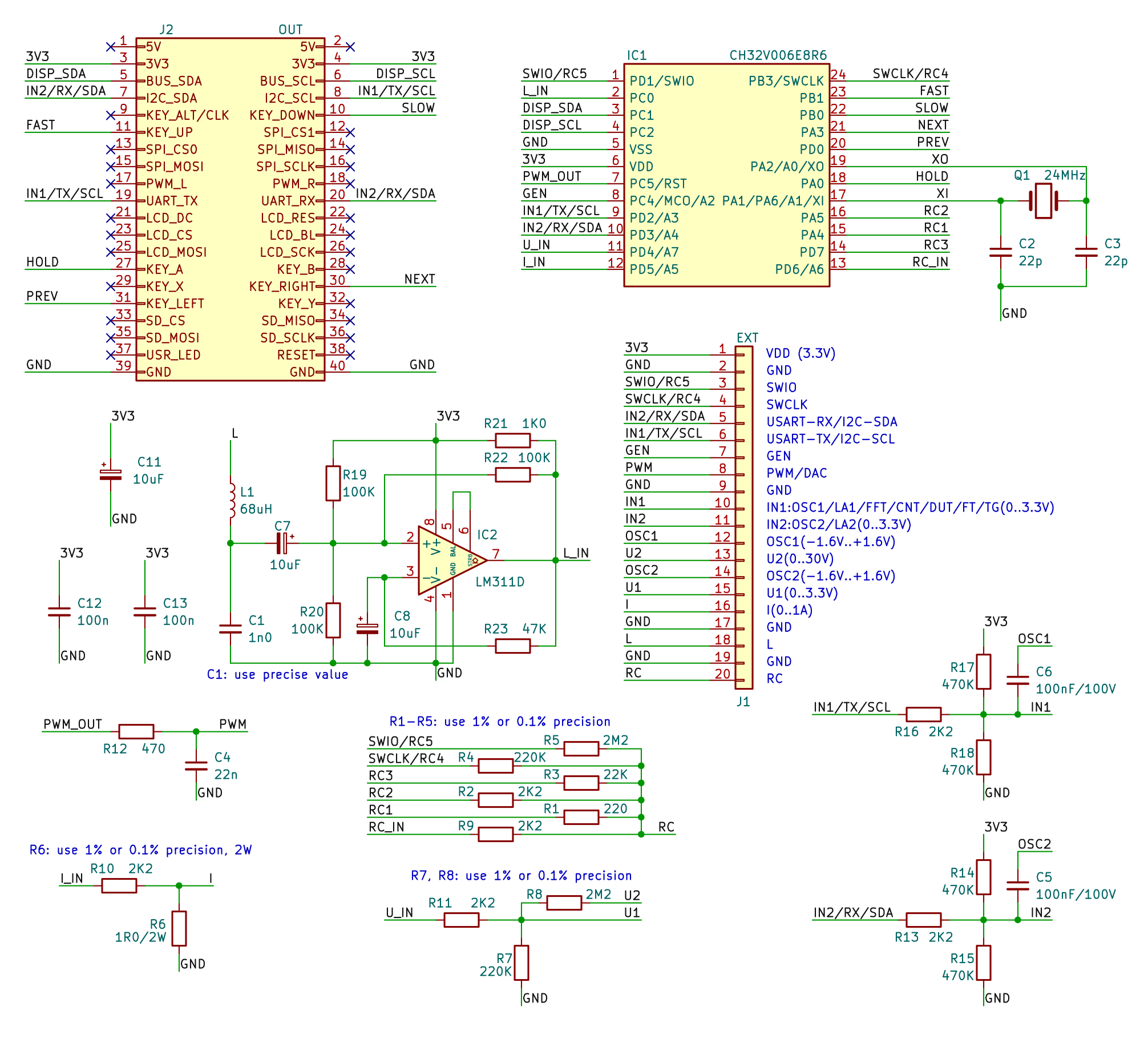
The "PidiMet" module is used to build a universal multimeter PidiMet. The "Base", "OLED128x64" and "KeyPad" modules need to be connected to the module. The "PidiMetAdapter" adapter can be used to connect the measuring leads. When constructing this module, I would like to point out that some components are too close together and are difficult to solder - it might be better to rearrange the board slightly and also choose larger housings for the capacitors. Firmware for the "PidiMet" module can be found in the CH32LibSDK library in the ch32\DEVICE\PidiMet folder www GitHub, or as a standalone project www GitHub.
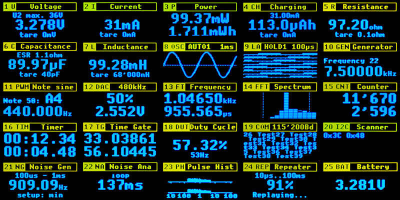
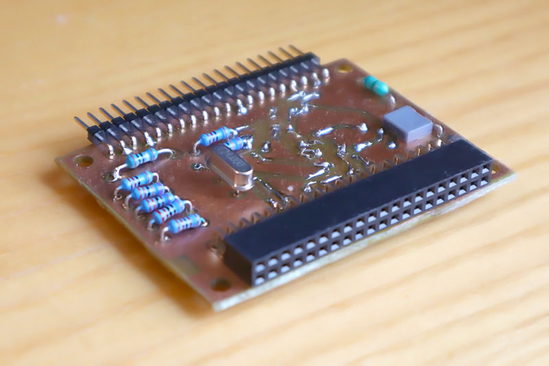
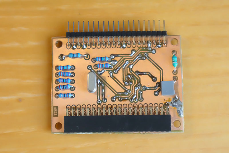
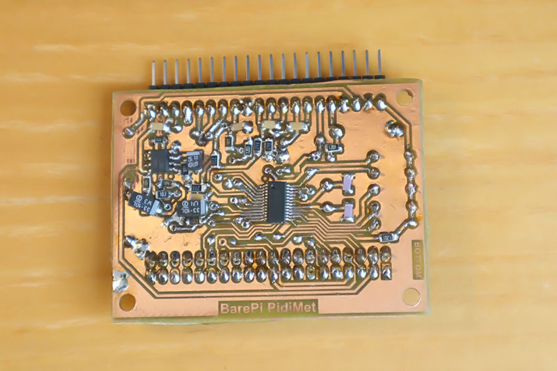
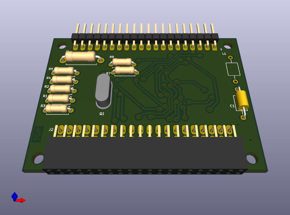
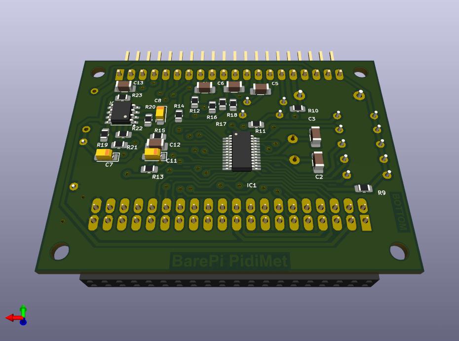
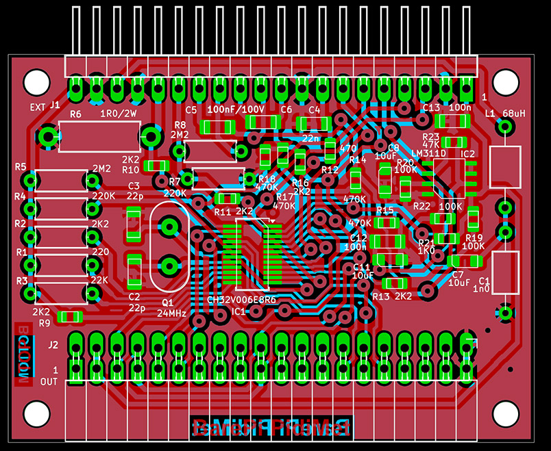
PidiMet multimeter built from BarePi modules:
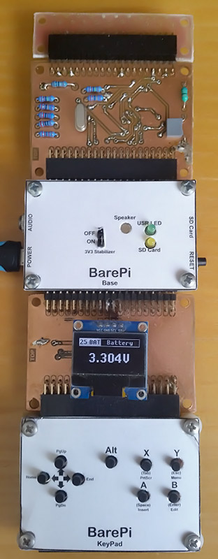
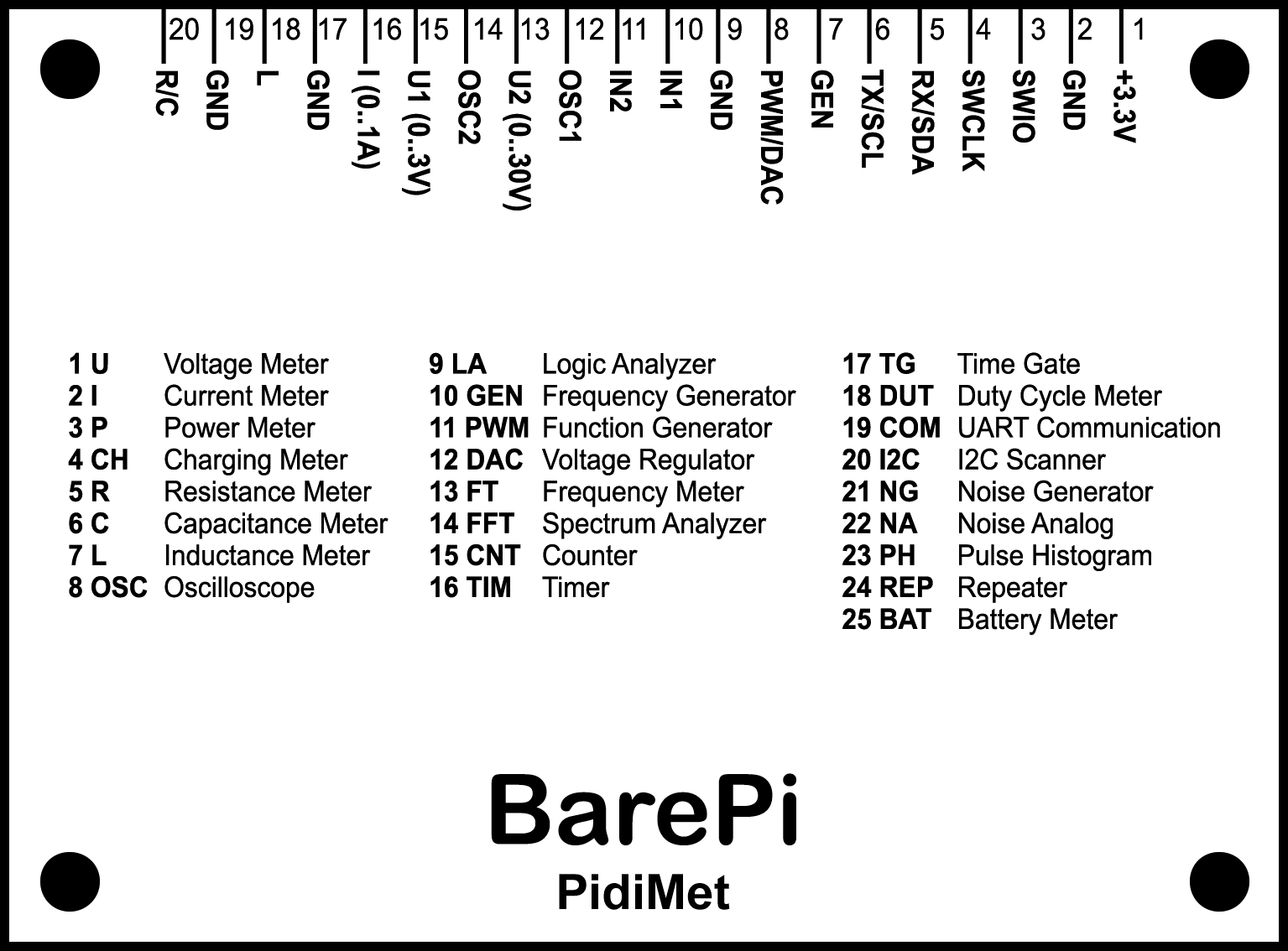
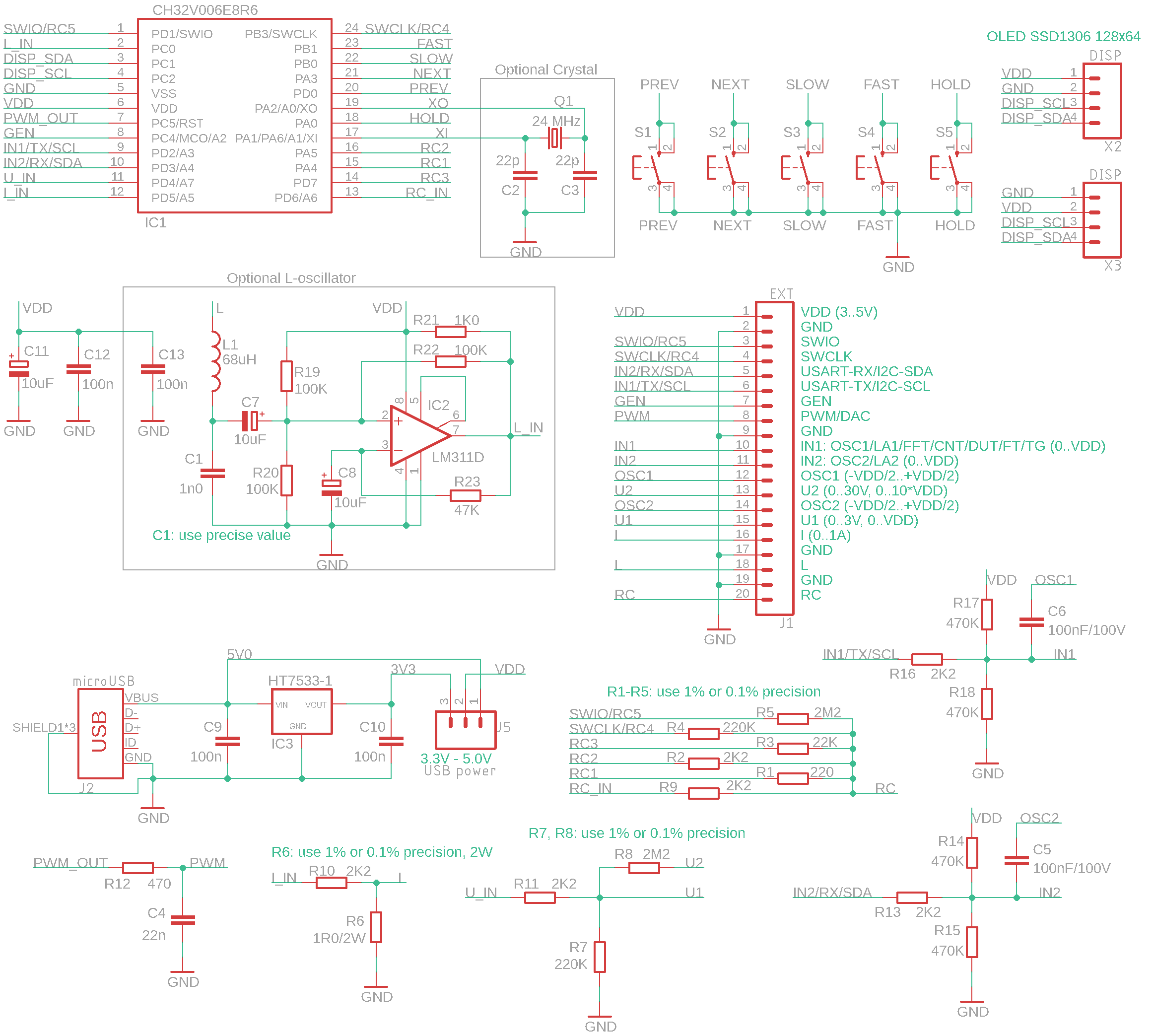
PidiMet multimeter wiring diagram:
The "PidiMetAdapter" module is an adapter for connecting measuring leads to the "PidiMet" module.
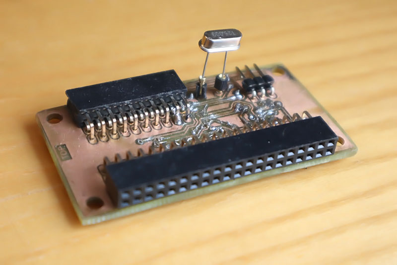
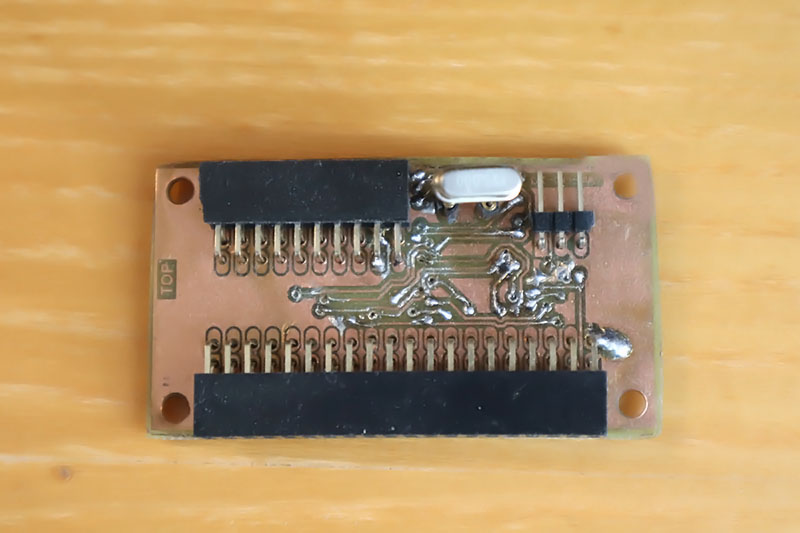
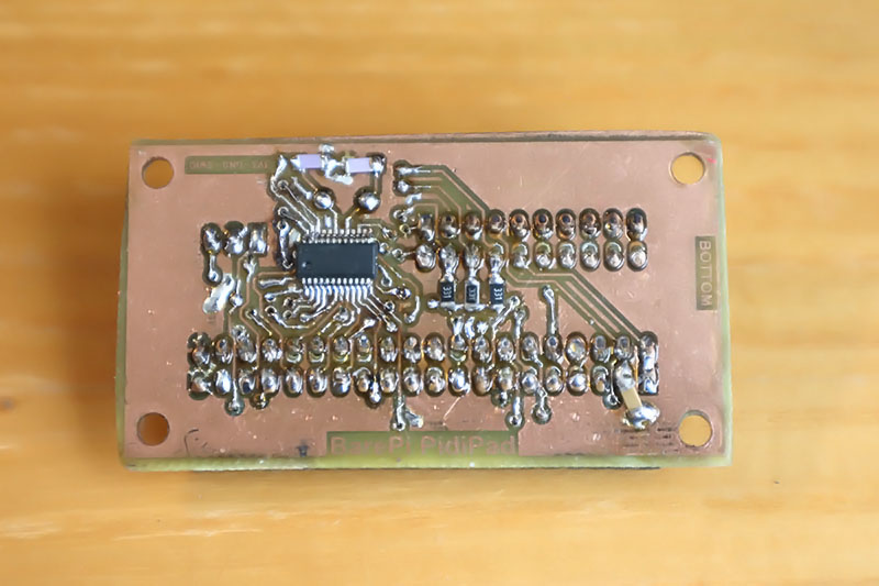
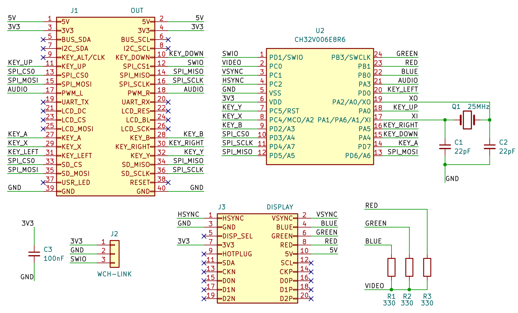
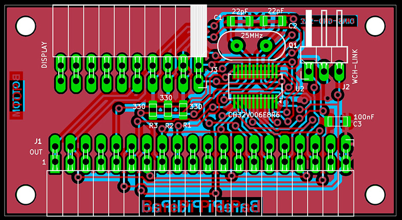
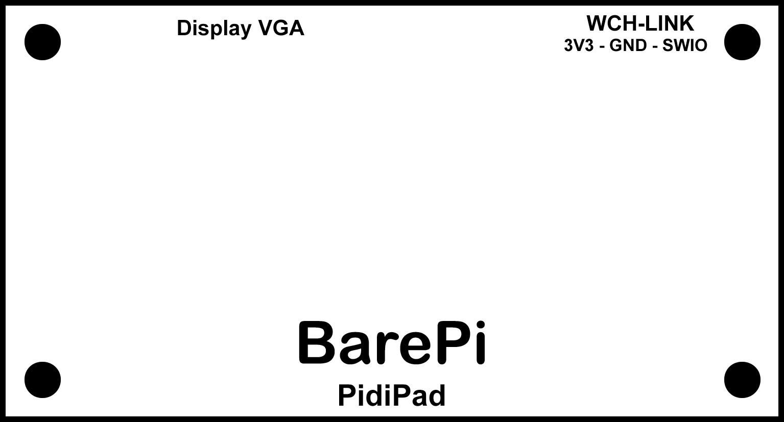
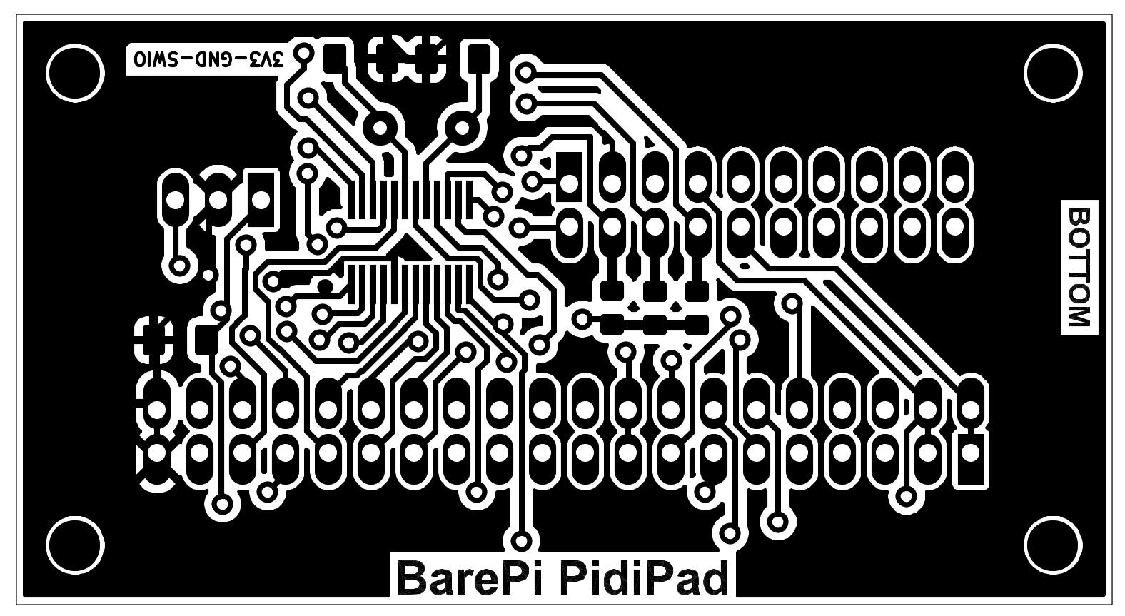
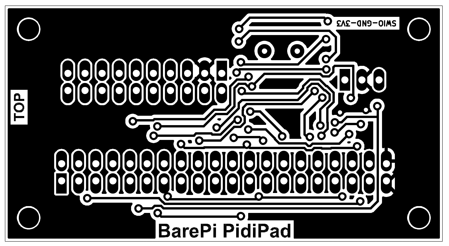
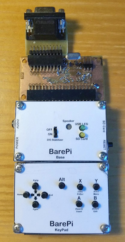
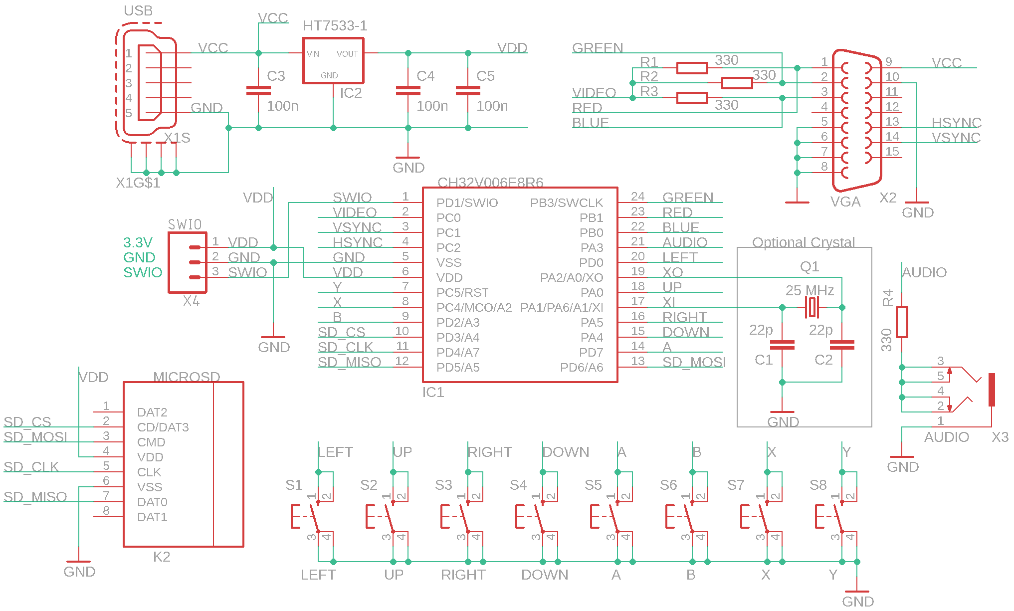
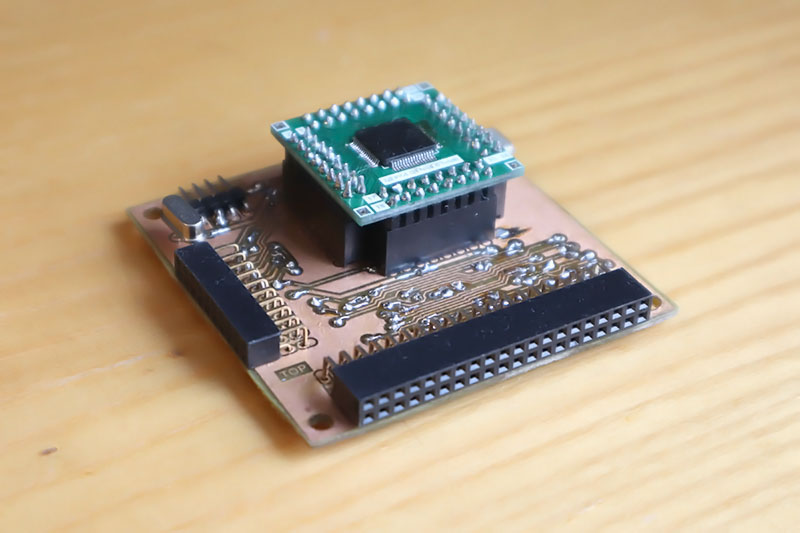
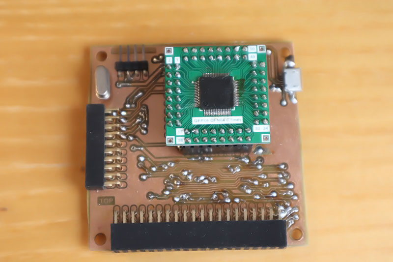
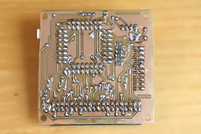
The "PidiPad" module is used to build a PidiPad game console, with a CH32V006E8R6 processor and VGA monitor output. The "DispVGA", "Base" and "KeyPad" modules need to be connected to the module. If you do not use a 25 MHz crystal, the processor will choose a lower-precision RC oscillator - the console will still be usable, but the VGA image will slightly waver and shake. For this reason, the crystal is placed in a socket so that it can be removed and tested without the crystal. The PidiPad console in the CH32LibSDK library, where you can also find sample applications: www, GitHub.
Recommendation: Outputting video to a VGA monitor causes large current spikes in the power supply. Consider adding a tantalum capacitor to the processor's power supply; otherwise, the processor may operate at the limit of stability.
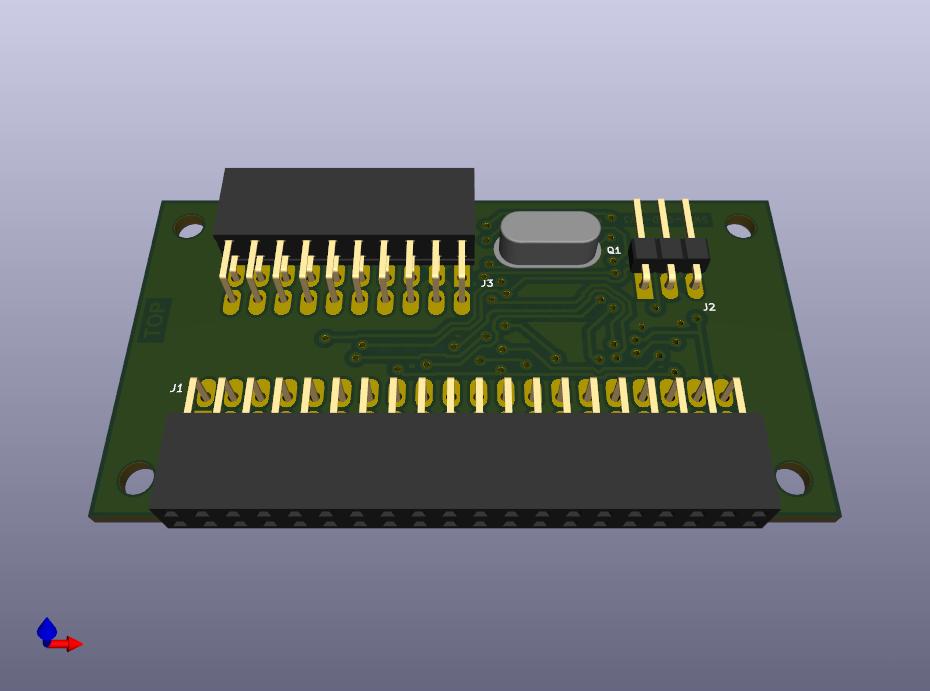
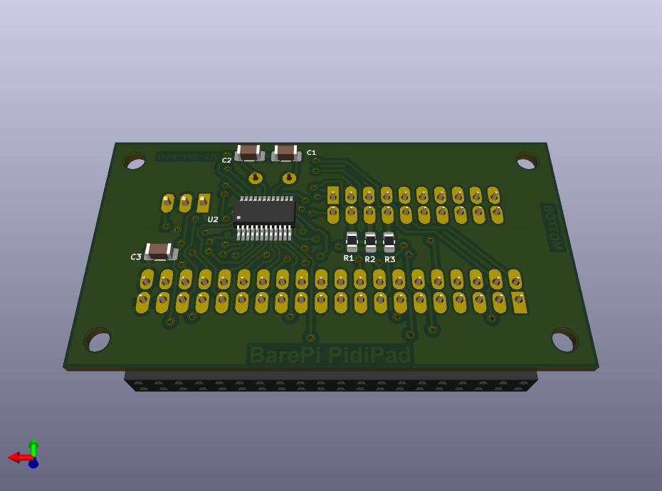
PidiPad console built from BarePi modules:
PidiPad console wiring diagram:
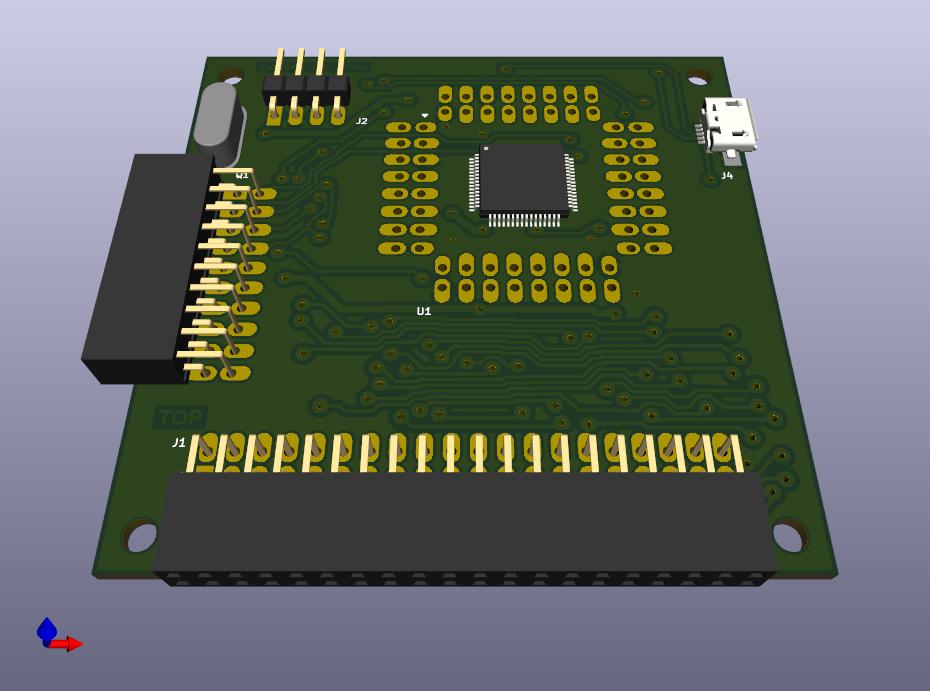
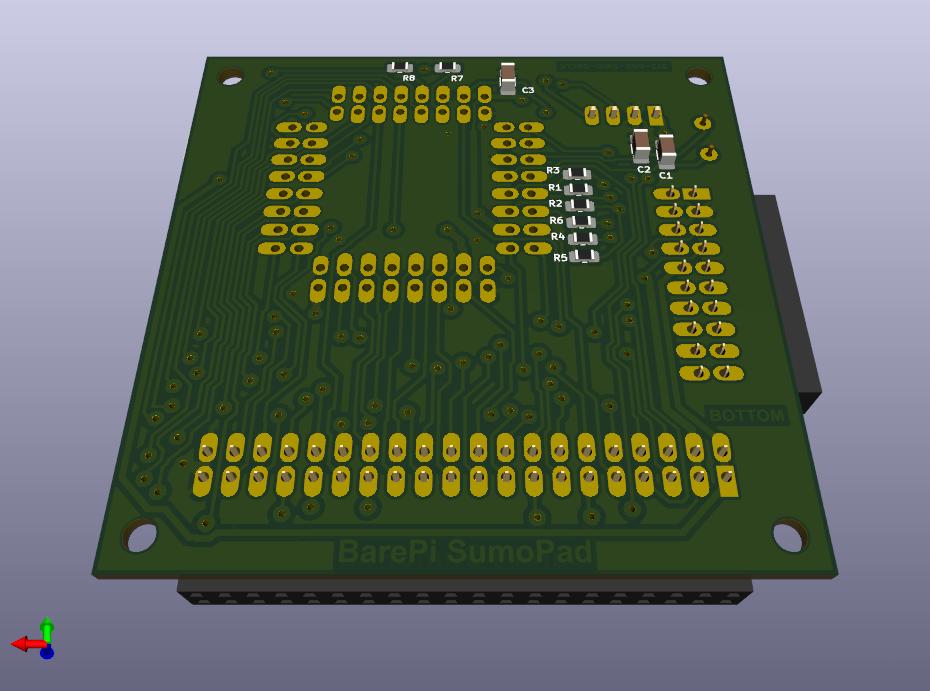
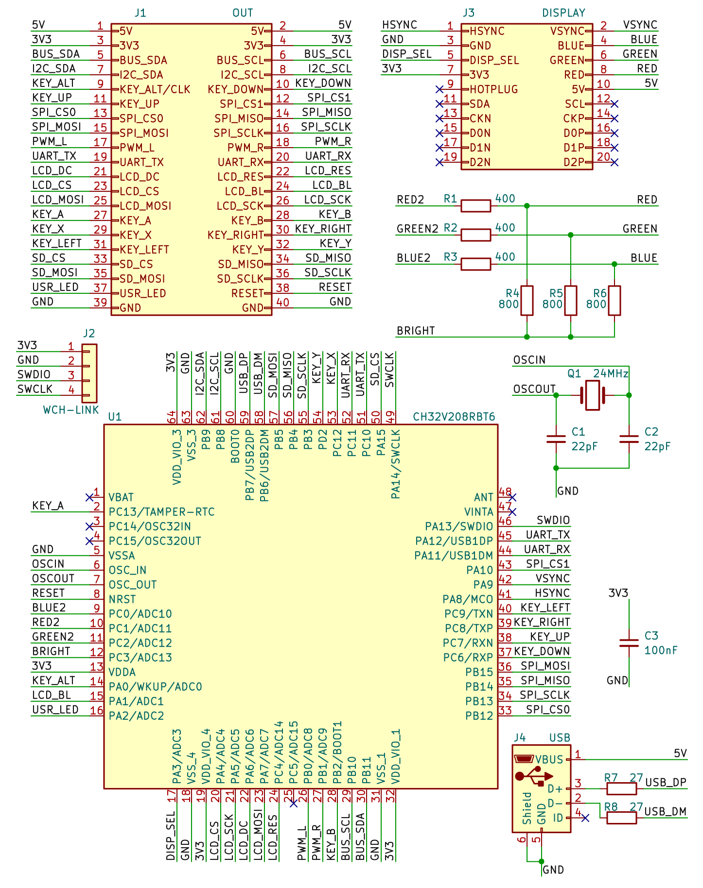
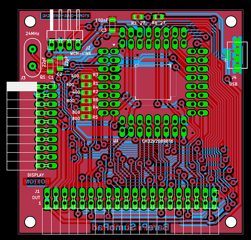
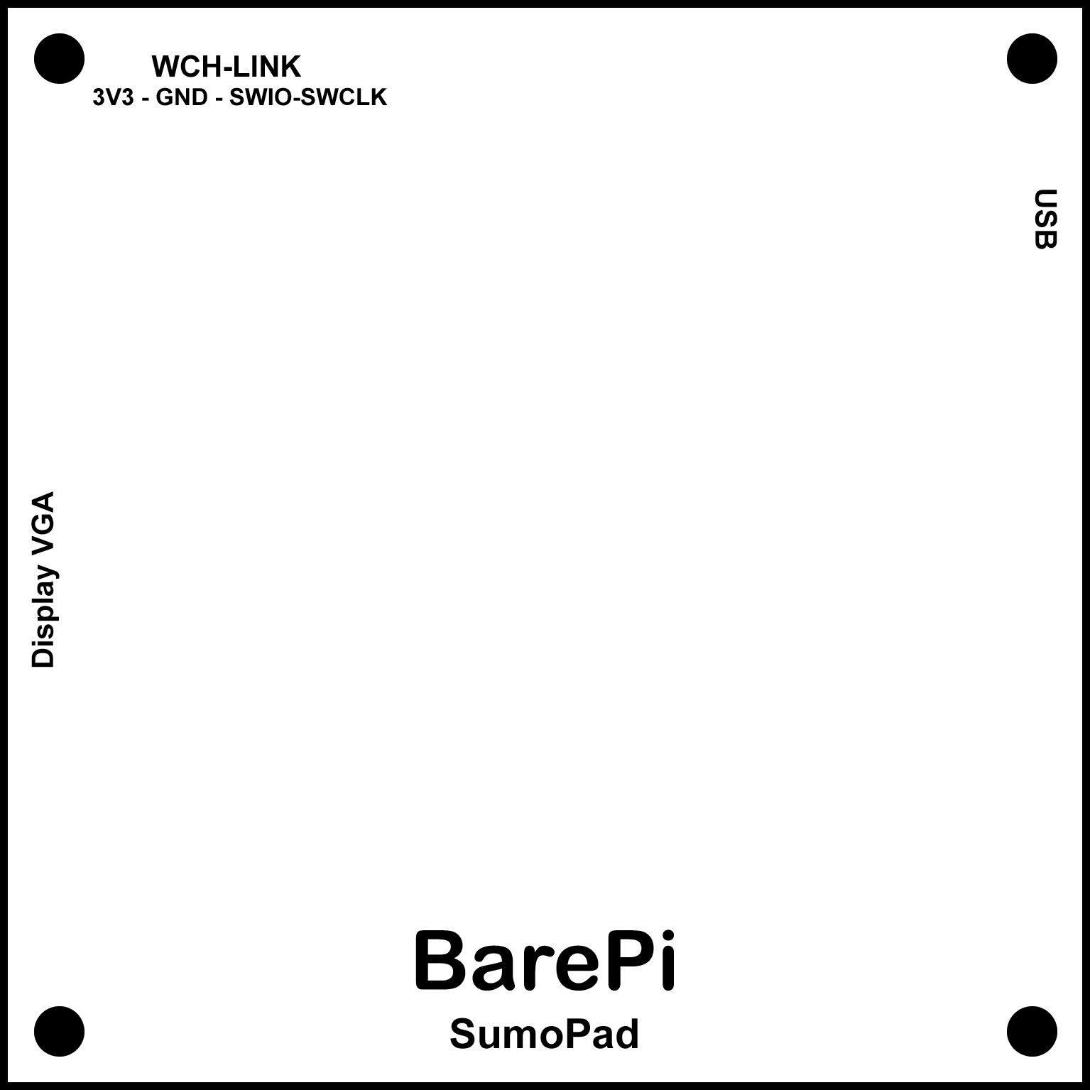
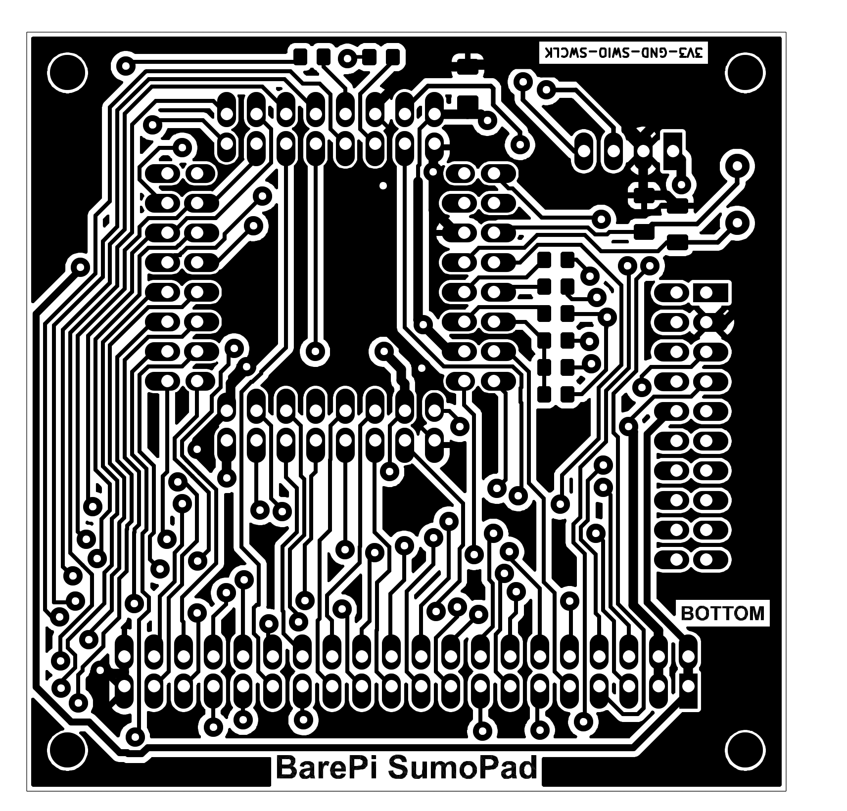
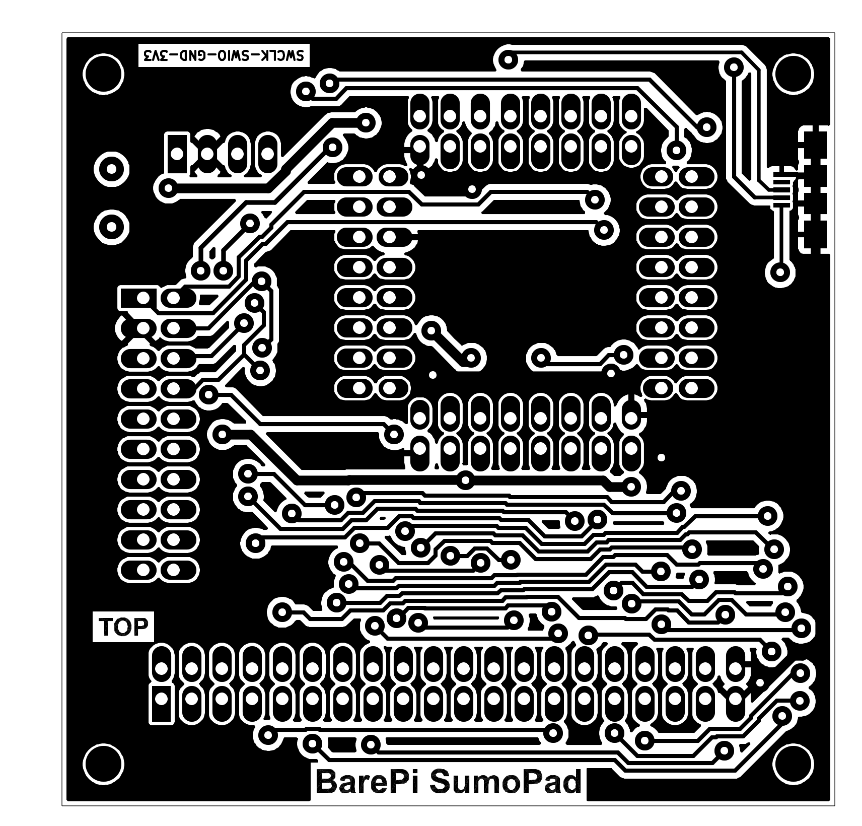
The "SumoPad" module is used to build the SumoPad game console. The "DispVGA", "LCD320x240", "Base" and "KeyPad" modules need to be connected to the module. The heart of the module is the CH32V208RBT6 processor. Due to the difficulty of soldering it (and also due to the higher price), the processor does not have to be soldered directly to the module board, but can be soldered on an LQFP-64 adapter, so that the processor can be replaced and used in other modules. Image output is possible either to an external VGA monitor or to an internal LCD320x240 display - depending on whether the "DispVGA" adapter is inserted into the module or not. The processor is controlled by a 24MHz crystal, instead of the recommended 32MHz crystal - due to better crystal availability. The processor can be used in the usual way with a 24MHz crystal, the only difference is that the Ethernet and Bluetooth interfaces cannot be used - but these are not available in this module anyway. The crystal could be changed to the recommended 32MHz, in which case the PLL module settings must be adjusted in the software, or automatic crystal frequency detection must be added to the firmware.
The SumoPad console software is based on the CH32LibSDK library (links: www, GitHub), but the software for the SumoPad console is not yet ready.
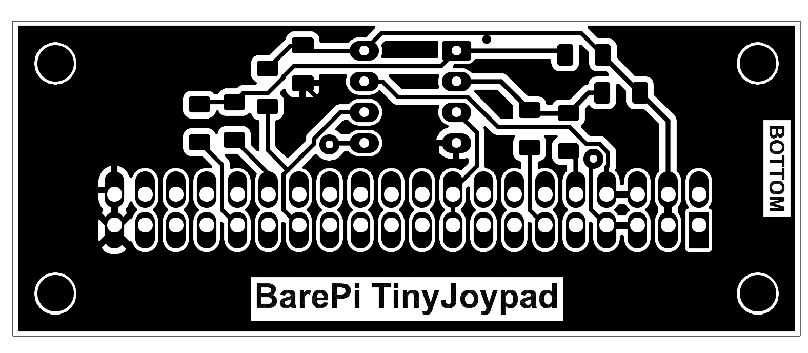
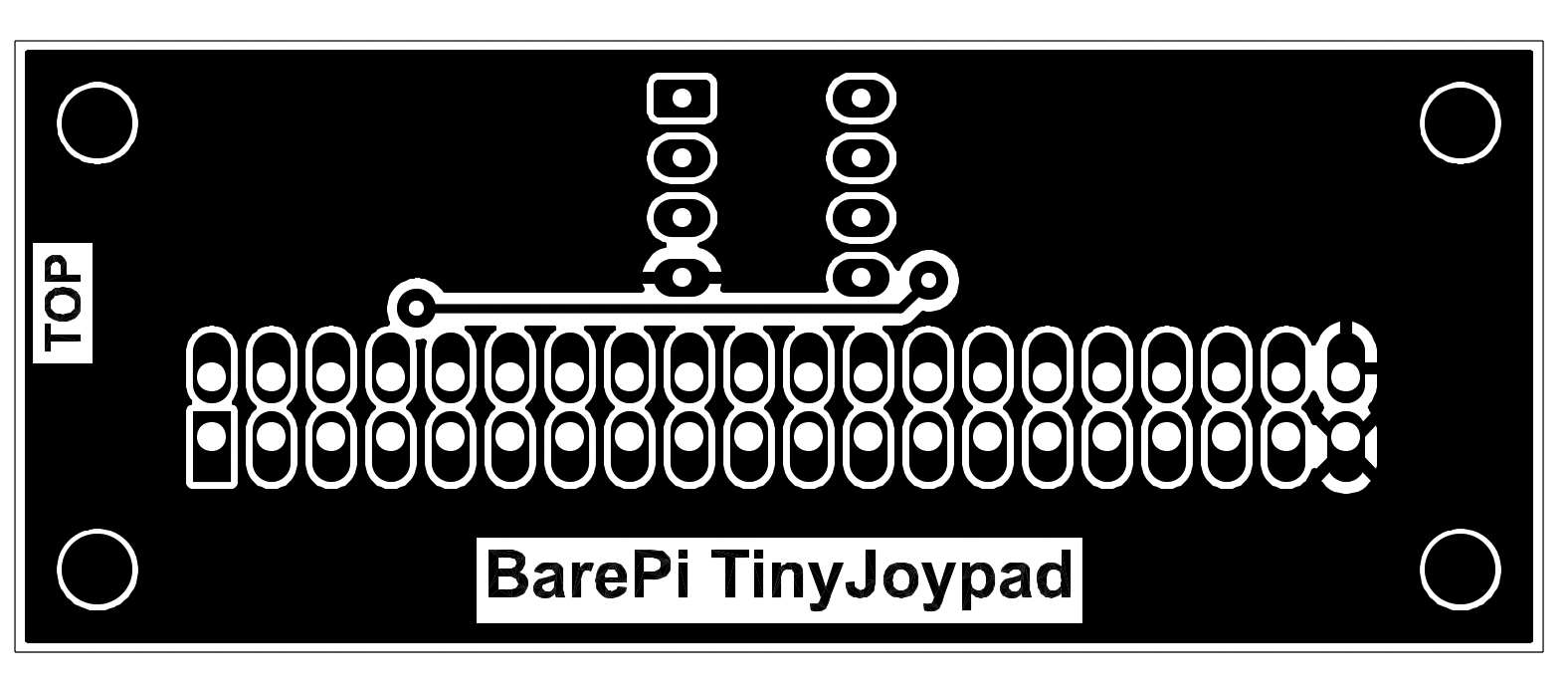
The "TinyJoypad" module is designed to control the "Tiny Joypad" game console, designed by (c) Daniel C (Electro L.I.B). The module contains an ATtiny85 processor. The program is loaded into the processor in a programmer, so it is advisable to use a DIL socket for the processor. The "Base", "OLED128x64" and "KeyPad" modules need to be connected to the module.
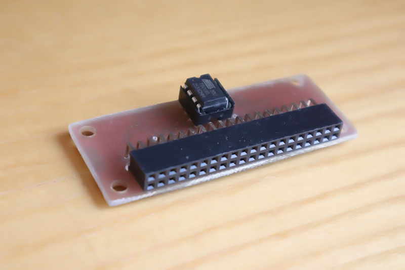
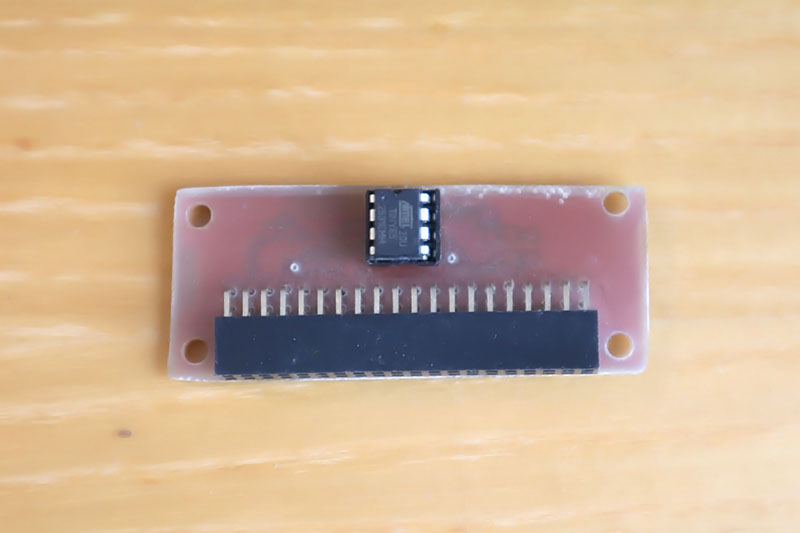
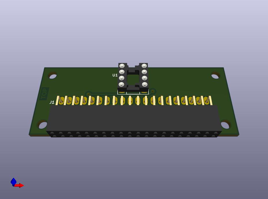
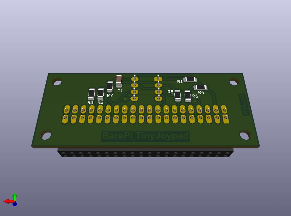
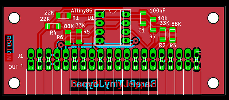
Tiny Joypad console built from BarePi modules:
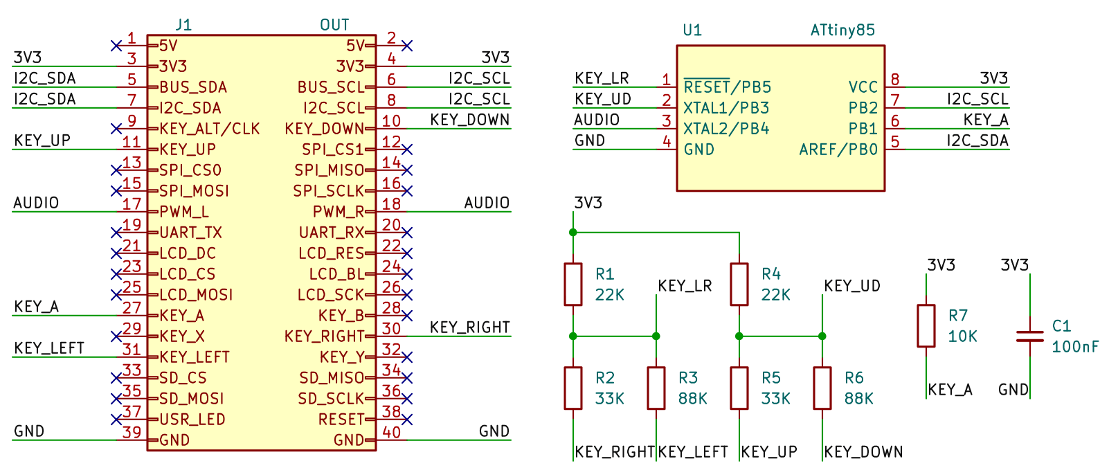
Tiny Joypad console wiring diagram:
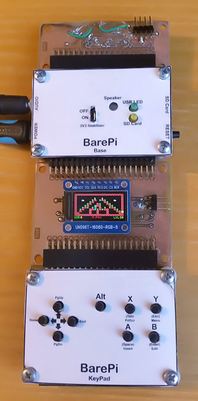
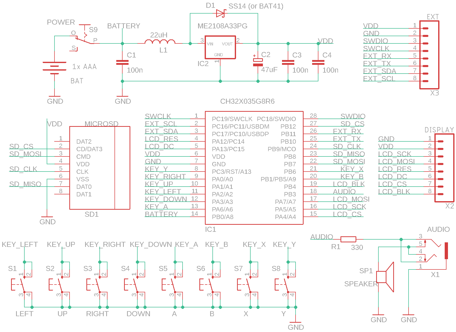
The "TweetyBoy" module is designed to build the TweetyBoy game console. The "LCD160x80", "Base" and "KeyPad" modules need to be connected to the module. The module is controlled by the CH32X035G8R6 processor. The TweetyBoy console in the CH32LibSDK library, where you can also find sample applications: www, GitHub.
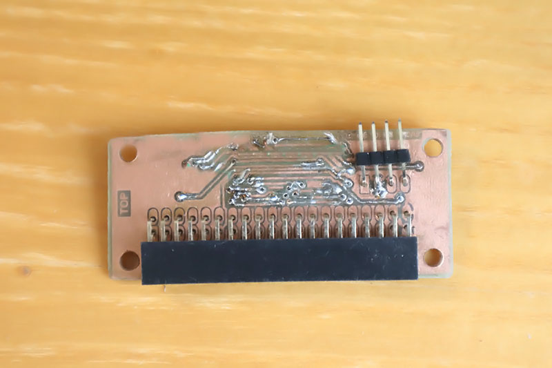
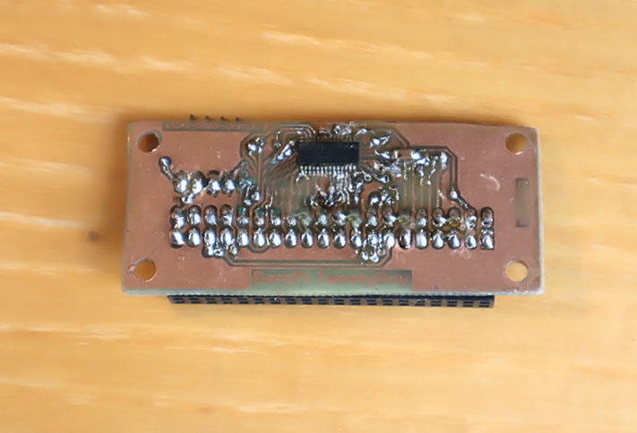
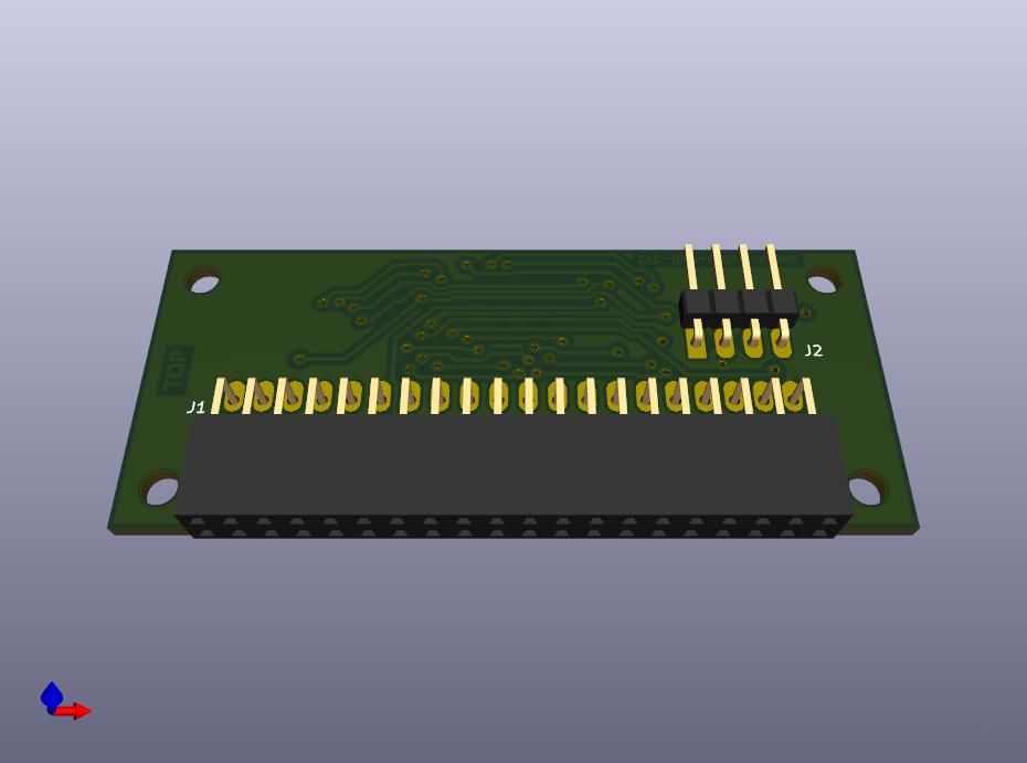
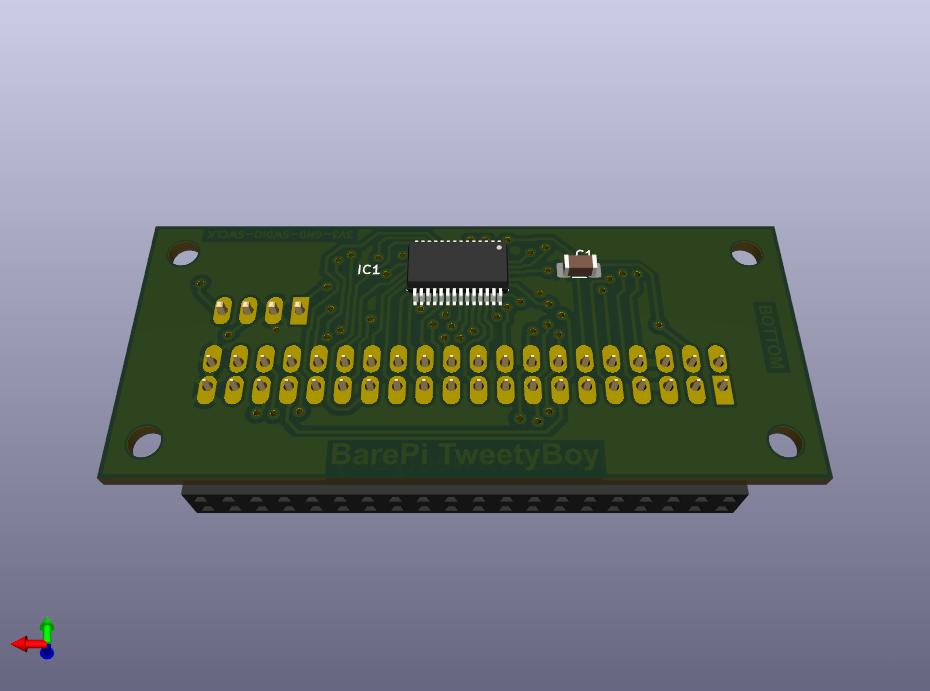
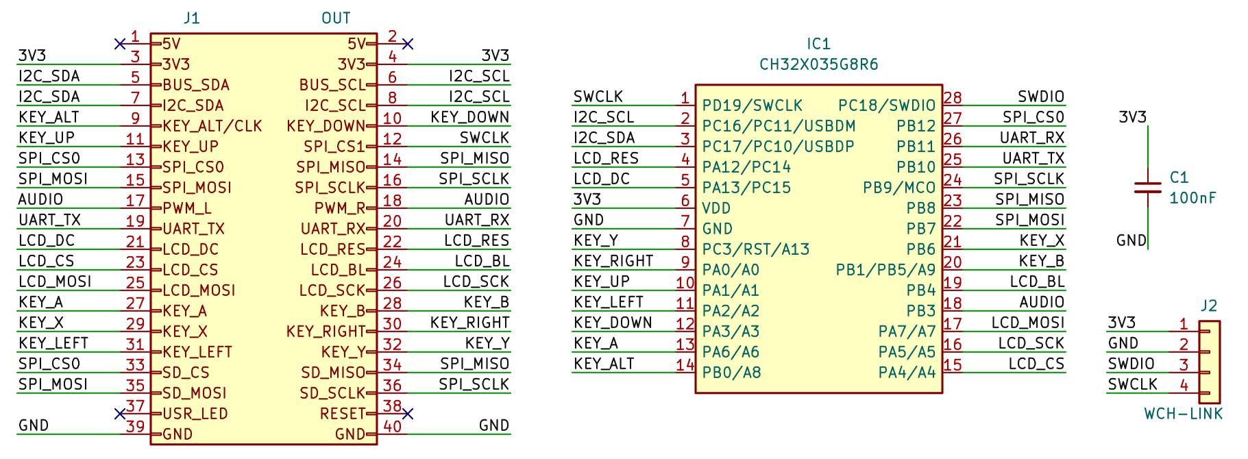
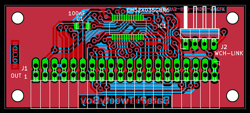
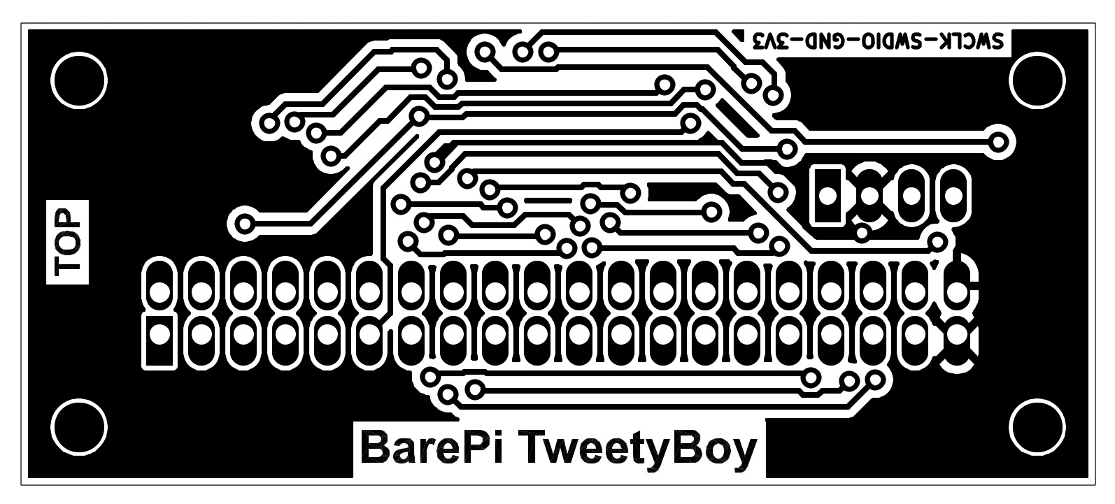
TweetyBoy console built from BarePi modules:
TweetyBoy console wiring diagram:
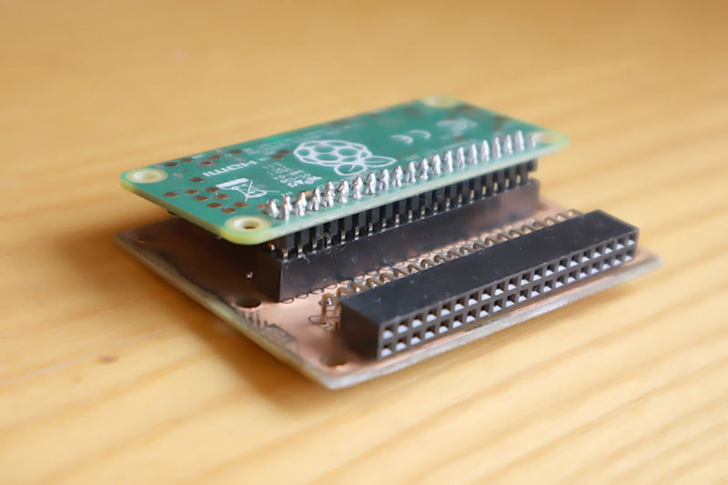
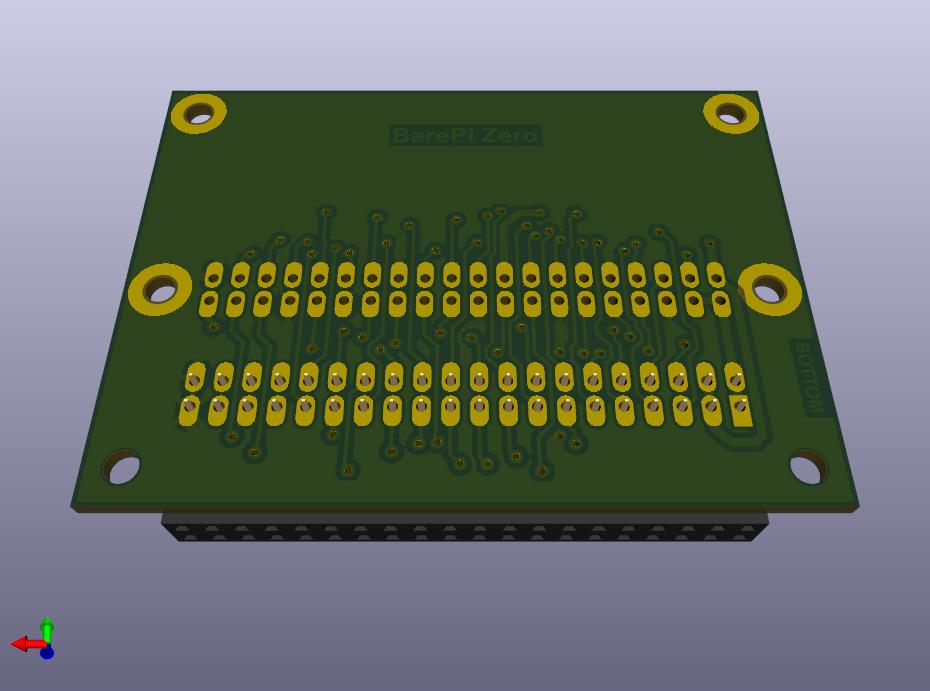
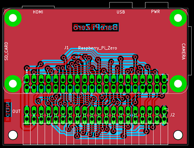
The "Zero" module is the highest type of processor module in the BarePi kit. It contains the Raspberry Zero 1 or Raspberry Zero 2 module. For easy replacement, I recommend fitting the module with a connector with a female strip, instead of hard soldering it over the pin strip. Unlike other modules, this module contains a USB connector for power and a microSD card, so it can be operated separately, without other modules. For PWM sound output, you may need to connect the "Base" module (I recommend disconnecting the internal stabilizer in the "Base" module with a jumper). For game control, you may need to connect the "KeyPad" module. The minimalist version of the game console is ZeroTiny - when using the kit modules, it corresponds to the connection of the "Zero", "Base" and "KeyPad" modules. The software for the "Zero" module uses the PiLibSDK library, which also includes sample applications: www, GitHub.
You can also connect other modules supported by the PiLibSDK library to the "Zero" module. If you connect the "LCD320x240" module, you can use the device with an LCD display instead of an HDMI monitor. The system automatically detects the LCD display and ensures that the image is sent to it. For a more detailed description of how to use the LCD display, see the "Intrd" section of the PiLibSDK library. If you connect the "RTC" module, your programs will be able to use the real-time clock and EEPROM memory. The PiLibSDK library also includes drivers for other modules, such as the SSD1306 OLED displays.
ZeroTiny console built from BarePi modules:
ZeroTiny console wiring diagram:
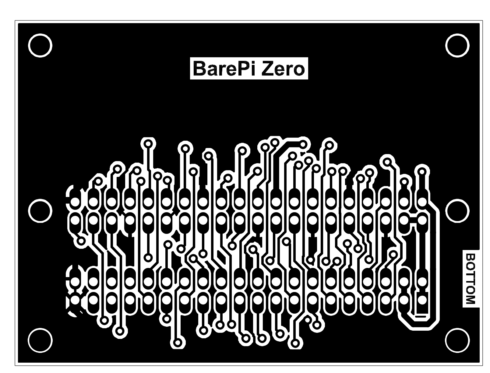
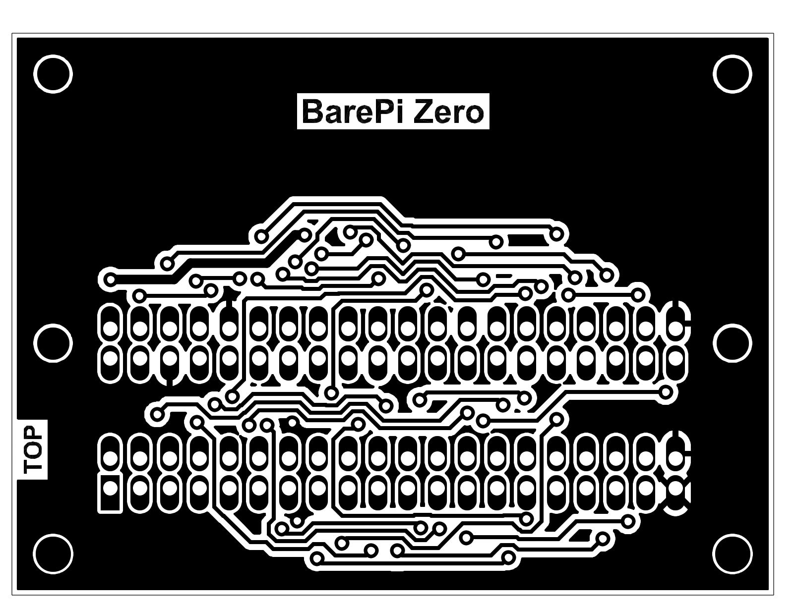
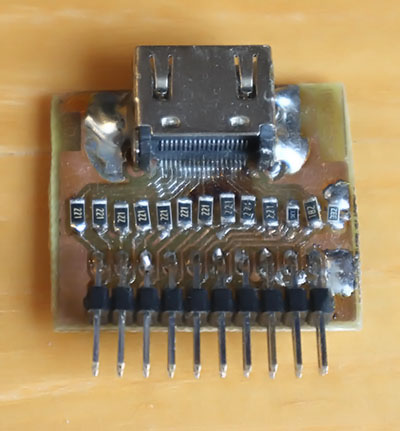
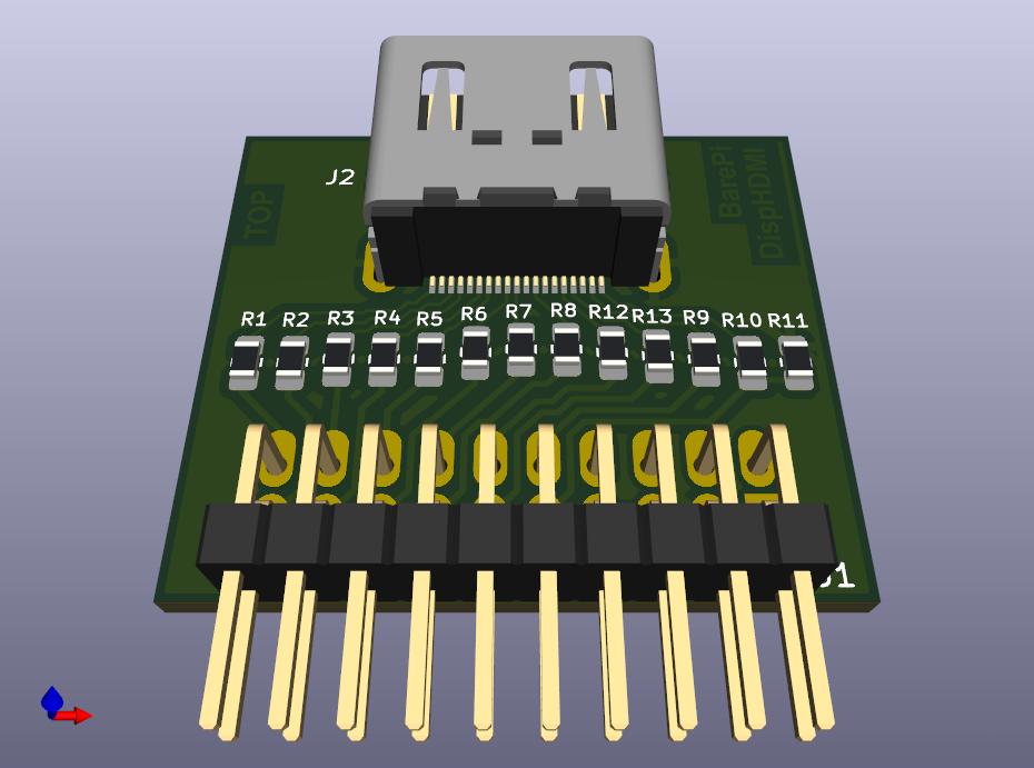
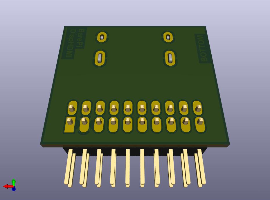
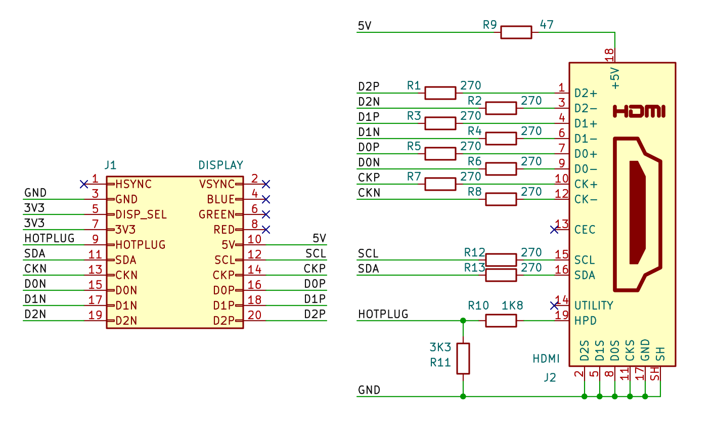
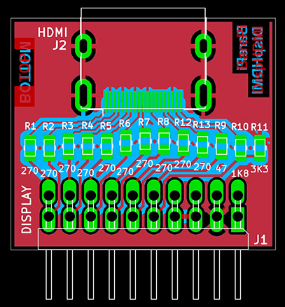
The "DispHDMI" module is a module for outputting images to a display with an HDMI interface. It is not a separate module with a bus, but an auxiliary module that can be connected to some processors using a connector with a 2x10-pin pin strip. The connector contains signals for output to both an HDMI display and a VGA display. In addition, it also contains a DISP_SEL signal used to detect whether a DispHDMI, DispVGA module is inserted into the connector or the connector is left free. Accordingly, the interface for an HDMI display, VGA display or internal LCD display can be selected.
The module also supplies the HOTPLUG, SCL and SDA signals to the display connector. Currently, no module uses these signals. Be careful when using the SCL and SDA signals - on most monitors, the signals are connected via pull-up resistors to +5V, which can be dangerous for circuits operating with 3.3V levels.
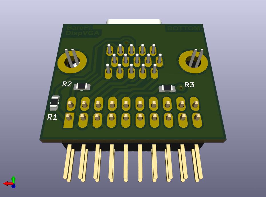
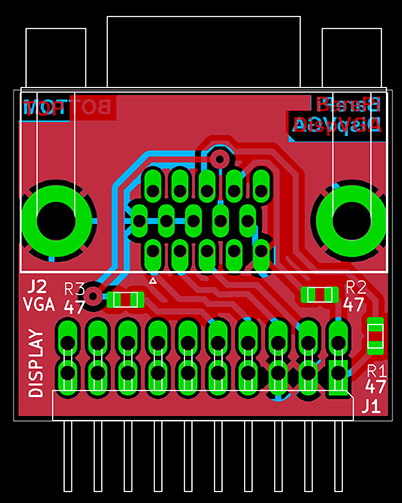
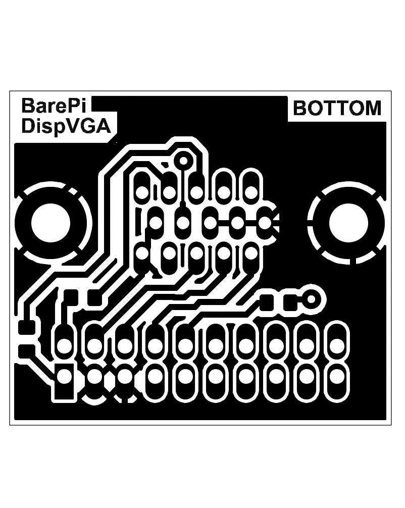
The "DispVGA" module is a module for outputting images to a display with a VGA interface. It is not a separate module with a bus, but an auxiliary module that can be connected to some processors using a connector with a 2x10-pin pin strip. The connector contains signals for output to both an HDMI display and a VGA display. In addition, it also contains a DISP_SEL signal used to detect whether a DispHDMI, DispVGA module is inserted into the connector or the connector is left free. Accordingly, the interface for an HDMI display, VGA display or internal LCD display can be selected.
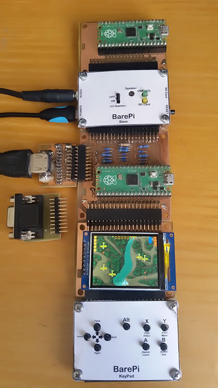
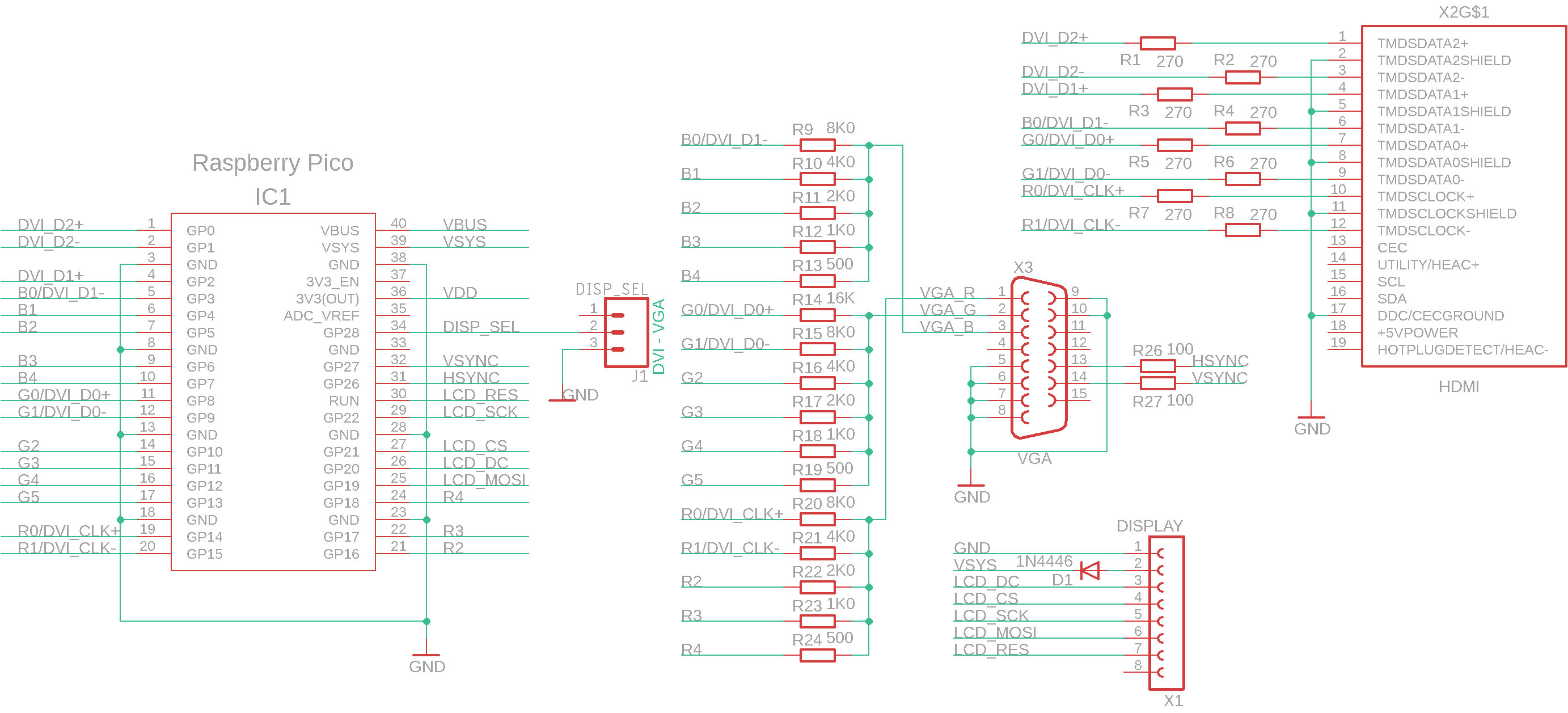
The "ExtDisp" module is designed to capture signals for an LCD display with an ST7789 controller and a resolution of 320x240 pixels, and display it on a VGA or HDMI monitor. The choice of monitor is determined by whether a DispVGA adapter or a DispHDMI adapter is inserted into the display connector. Firmware for the "ExtDisp" module can be found in the PicoLibSDK library in the !Pico\Module folder, file ExtDisp0.UF2 (version 0 with the Pico module): www, GitHub.
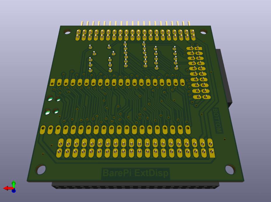
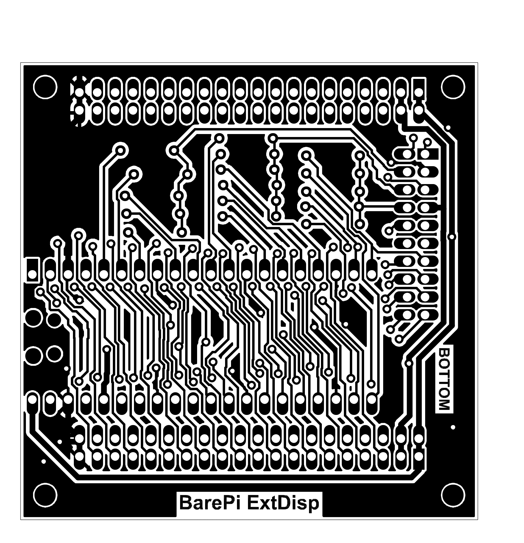
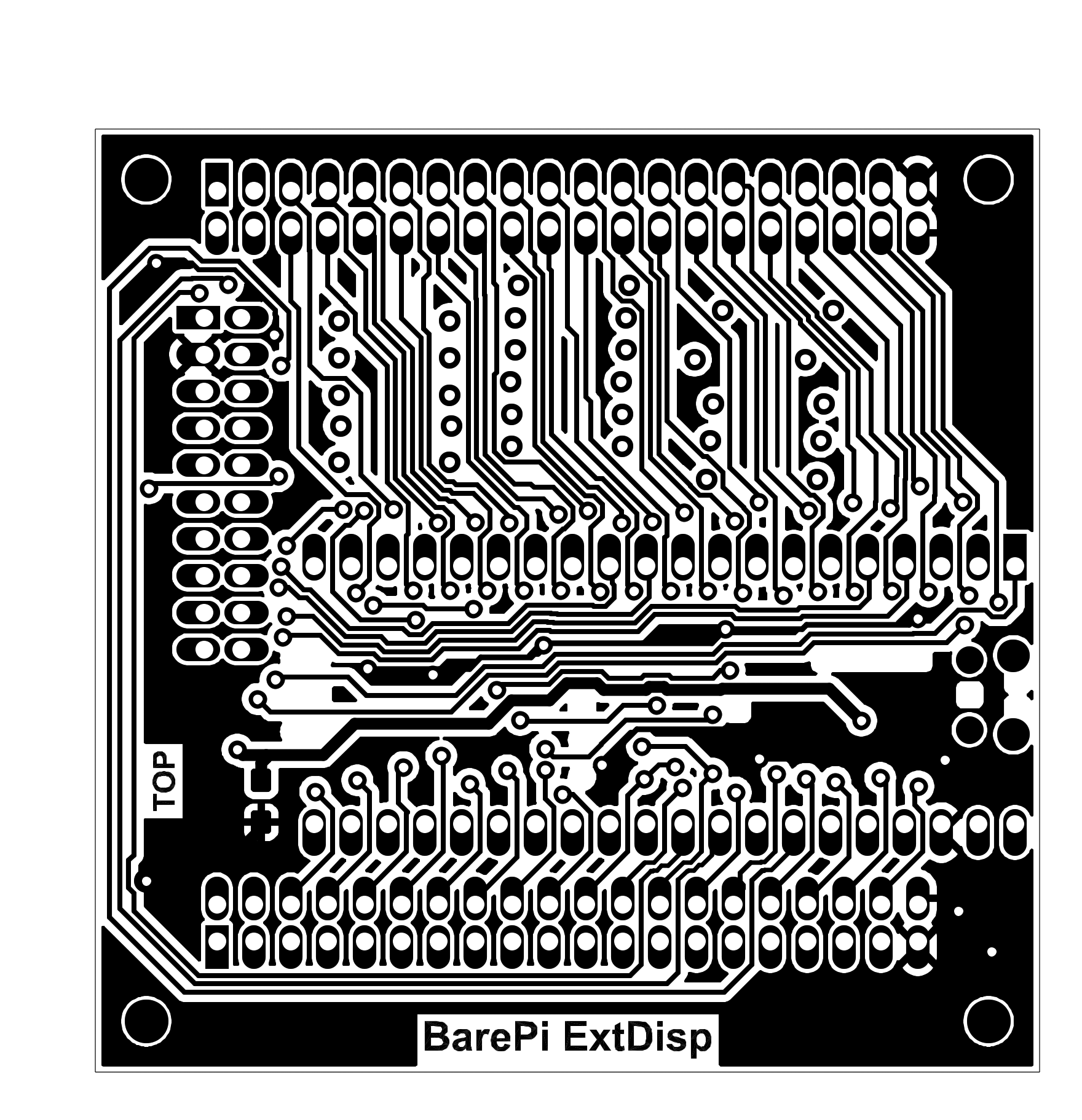
The ExtDisp module integrated into the PicoPad console:
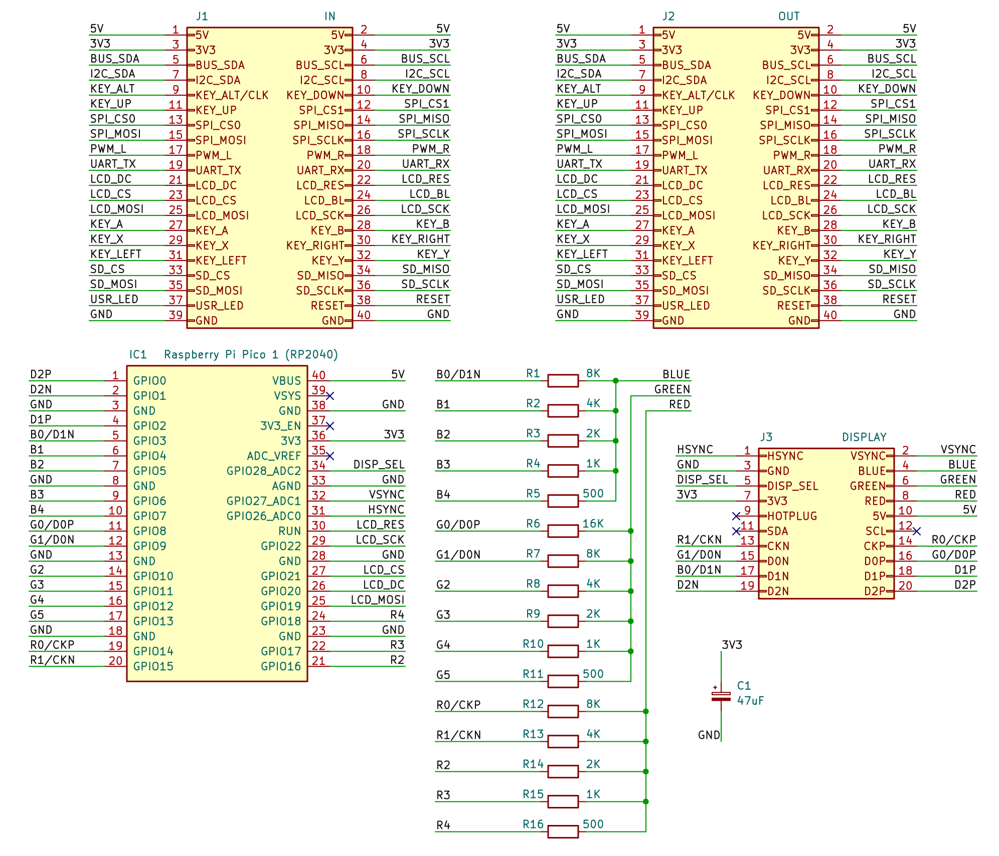
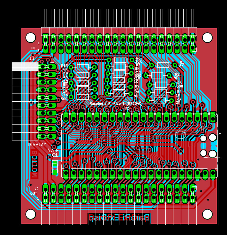
Wiring diagram for the original ExtDisp adapter version 0 (with the Pico module):
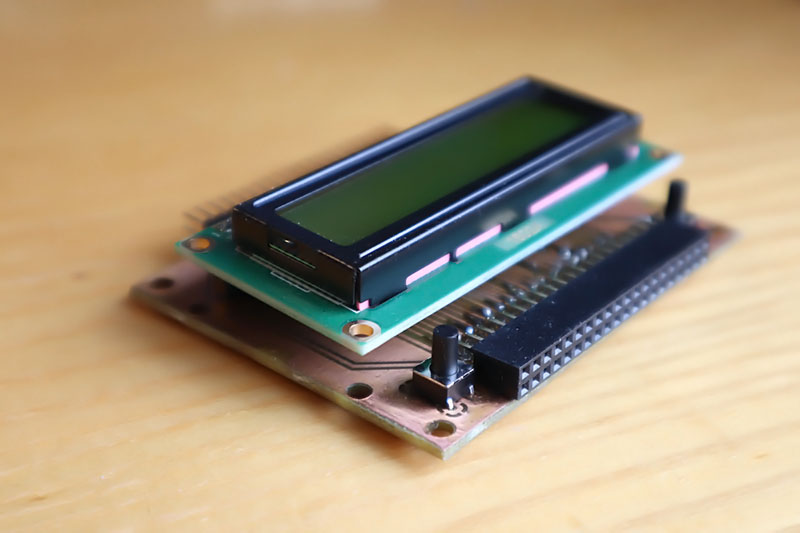
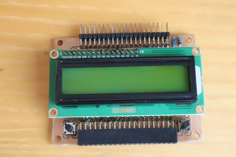
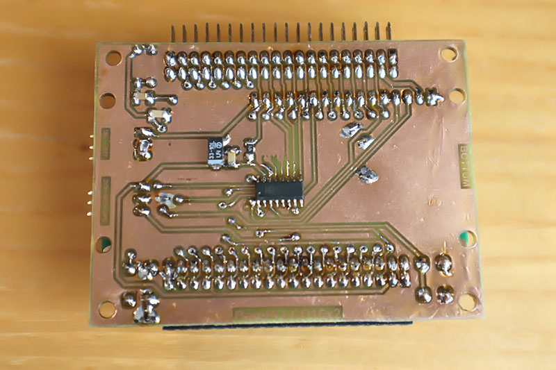
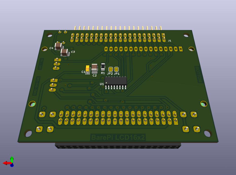
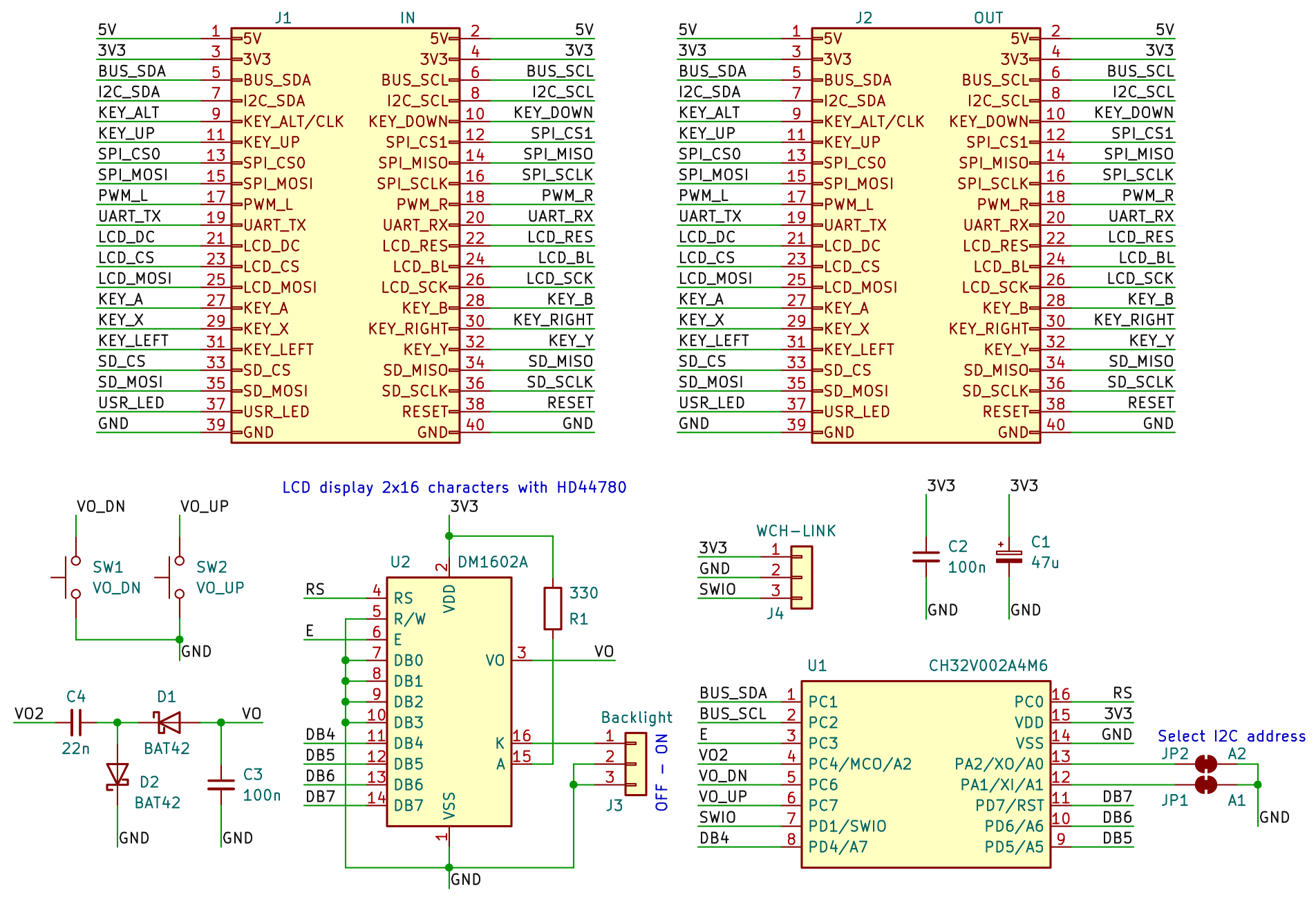
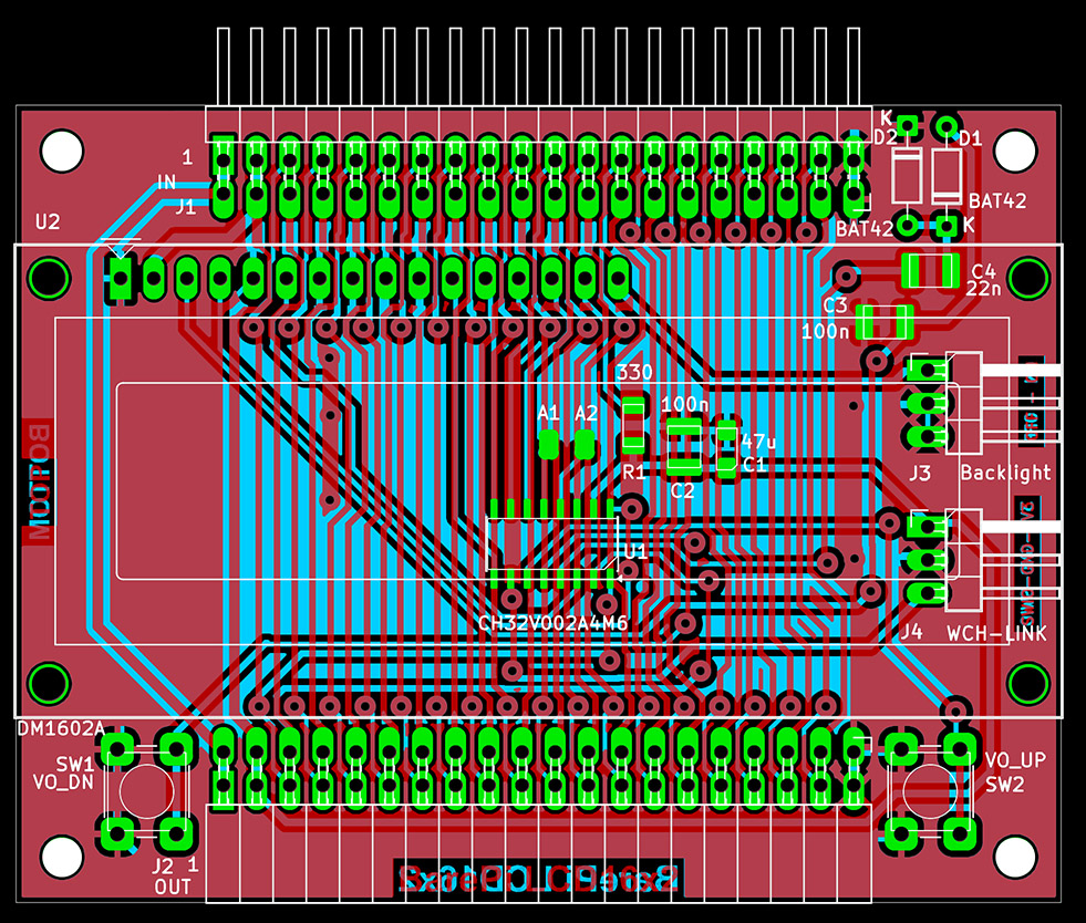
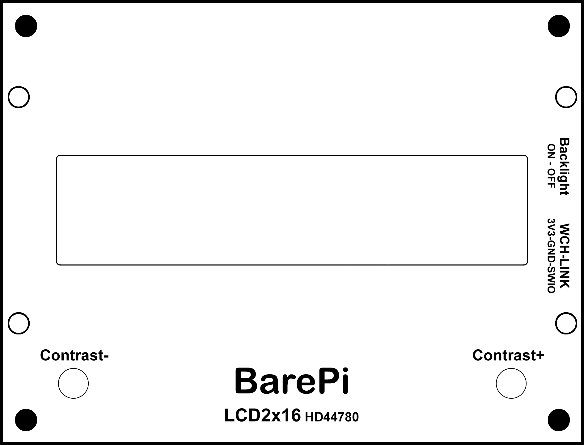
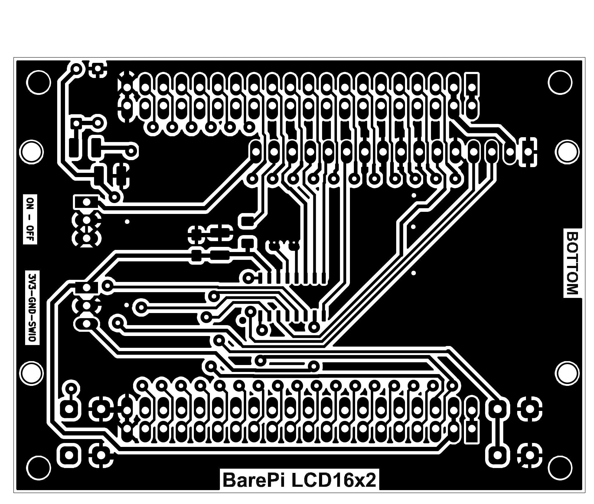
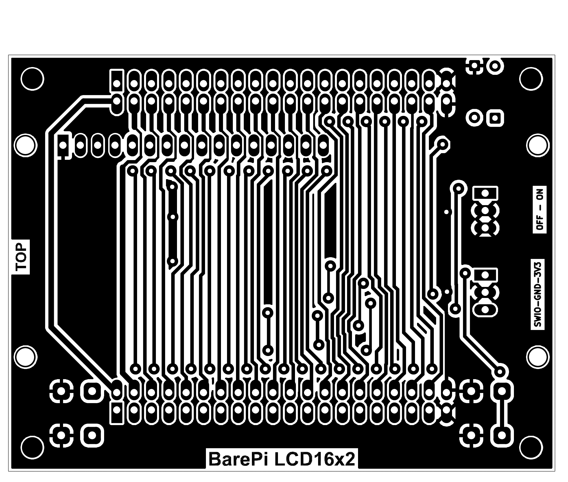
The "LCD16x2" module is a DM1602A text LCD display with 2 rows of 16 characters and an HD44780 controller. The module contains a CH32V002A4M6 processor, which is used to control the display and communicate with the main processor via the I2C bus. The auxiliary function of the processor is to generate a 5V bias voltage for the LCD display. The V0_DN and V0_UP buttons can be used to control the voltage level for the bias voltage, and thus the contrast of the LCD display. The display contrast, set using the buttons, is saved in the processor settings as the default value. The display contrast can also be controlled from the main processor - however, settings made from the main processor are not saved to permanent memory. The "Backlight" jumper can be used to turn the display backlight on or off. The processor is connected to the I2C bus at address 0x31. Although the module has two solder jumpers for selecting the I2C address, the firmware does not use these jumpers. The firmware allows you to redefine the font for 8 characters or select one of 5 predefined fonts. The default font also redefine 2 basic characters from the ASCII table (backslash and tilde), because some displays originally contain Japanese characters.
The processor firmware can be found in the CH32LibSDK library in the ch32\BAREPI\LCD16x2\ folder (GitHub: https://github.com/Panda381/CH32LibSDK/tree/main/ch32/BAREPI/LCD16x2 ).
In the PiLibSDK library, you’ll find the device driver in drv_lcdtxt.* (GitHub: https://github.com/Panda381/PiLibSDK/tree/main/_drv ).
In the PiLibSDK library, you’ll find the test program in Apps\TEST\LCD16X2 (GitHub: https://github.com/Panda381/PiLibSDK/tree/main/Apps/TEST/LCD16X2 ).

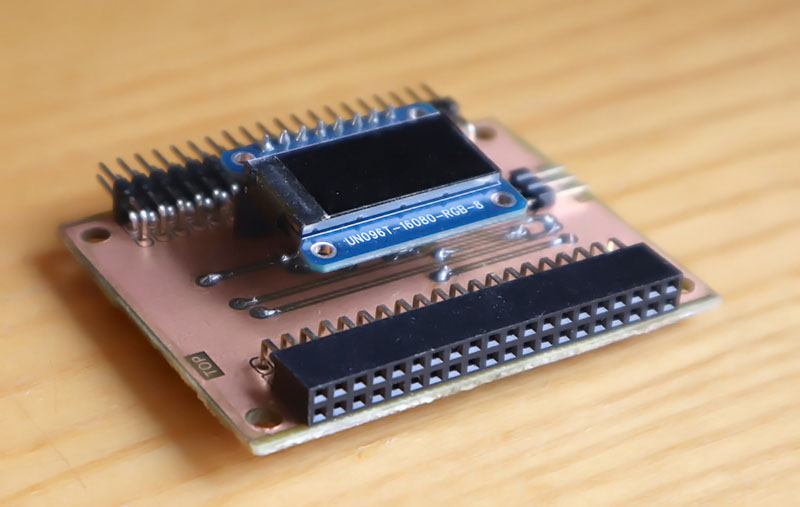
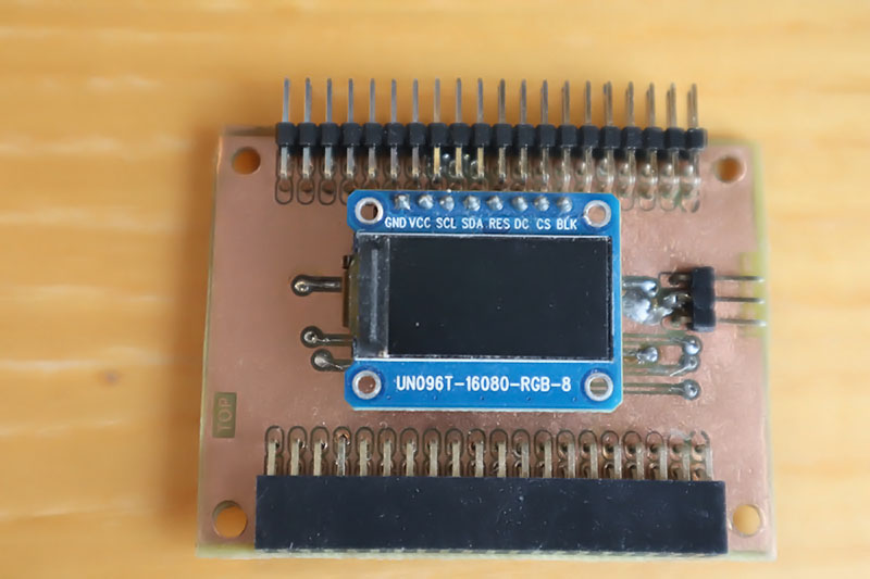
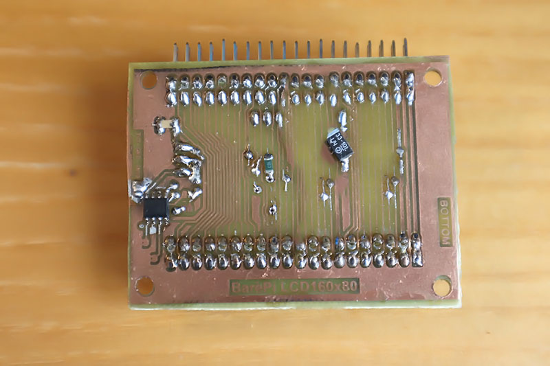
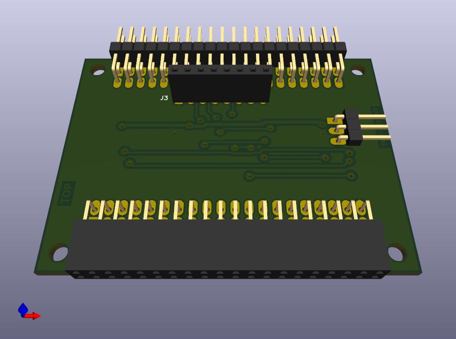
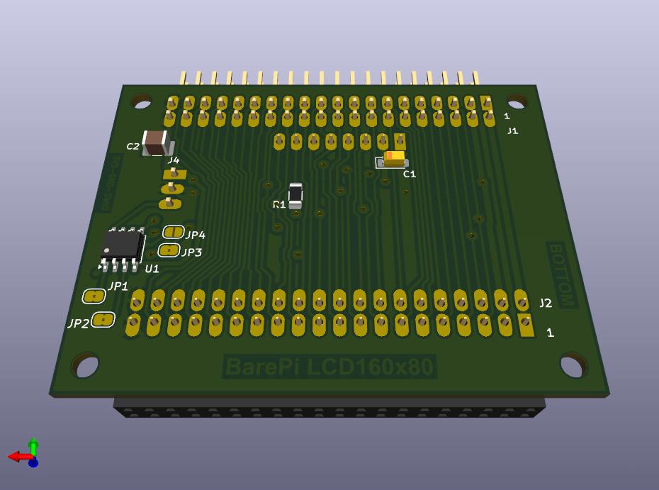
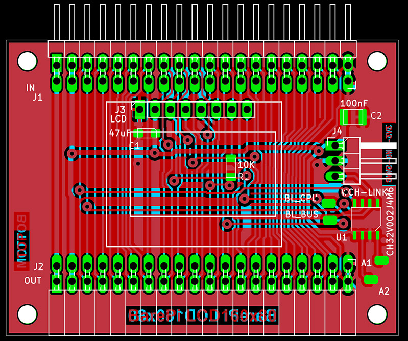
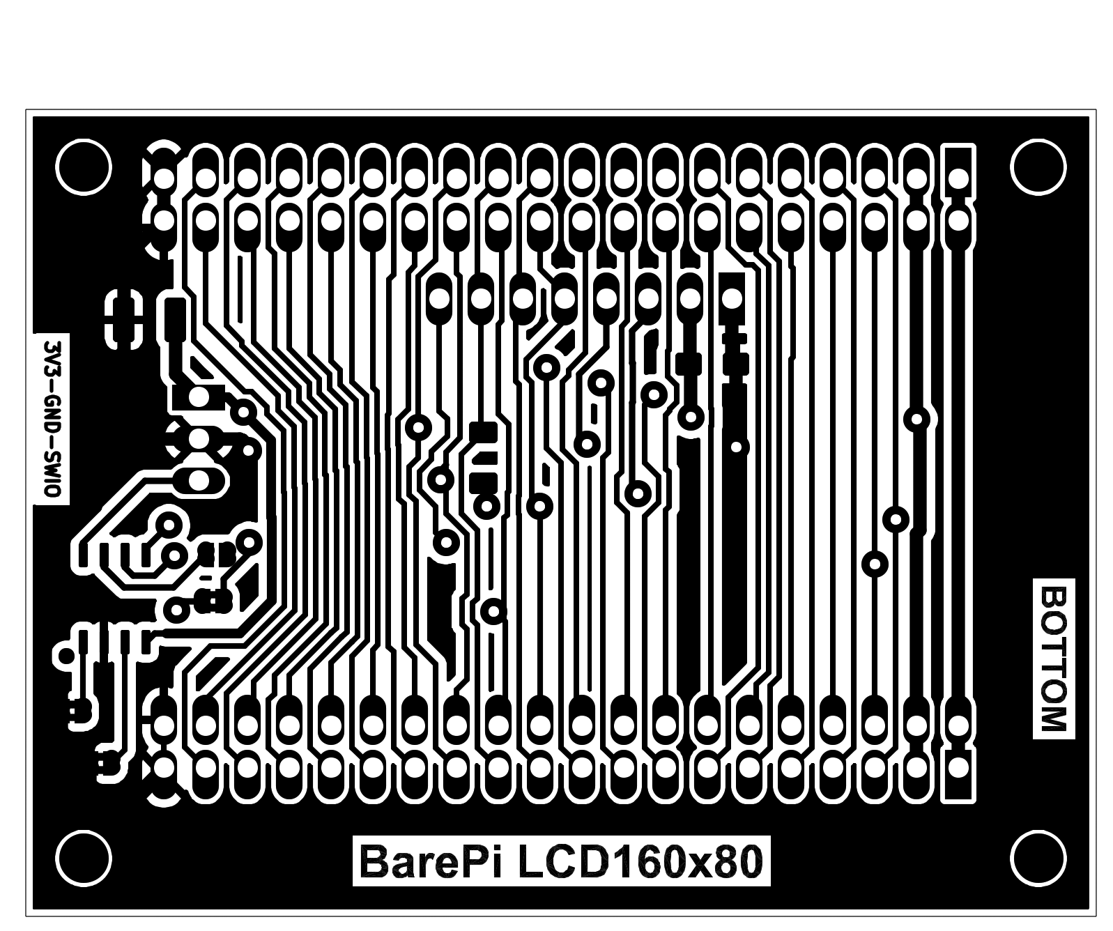
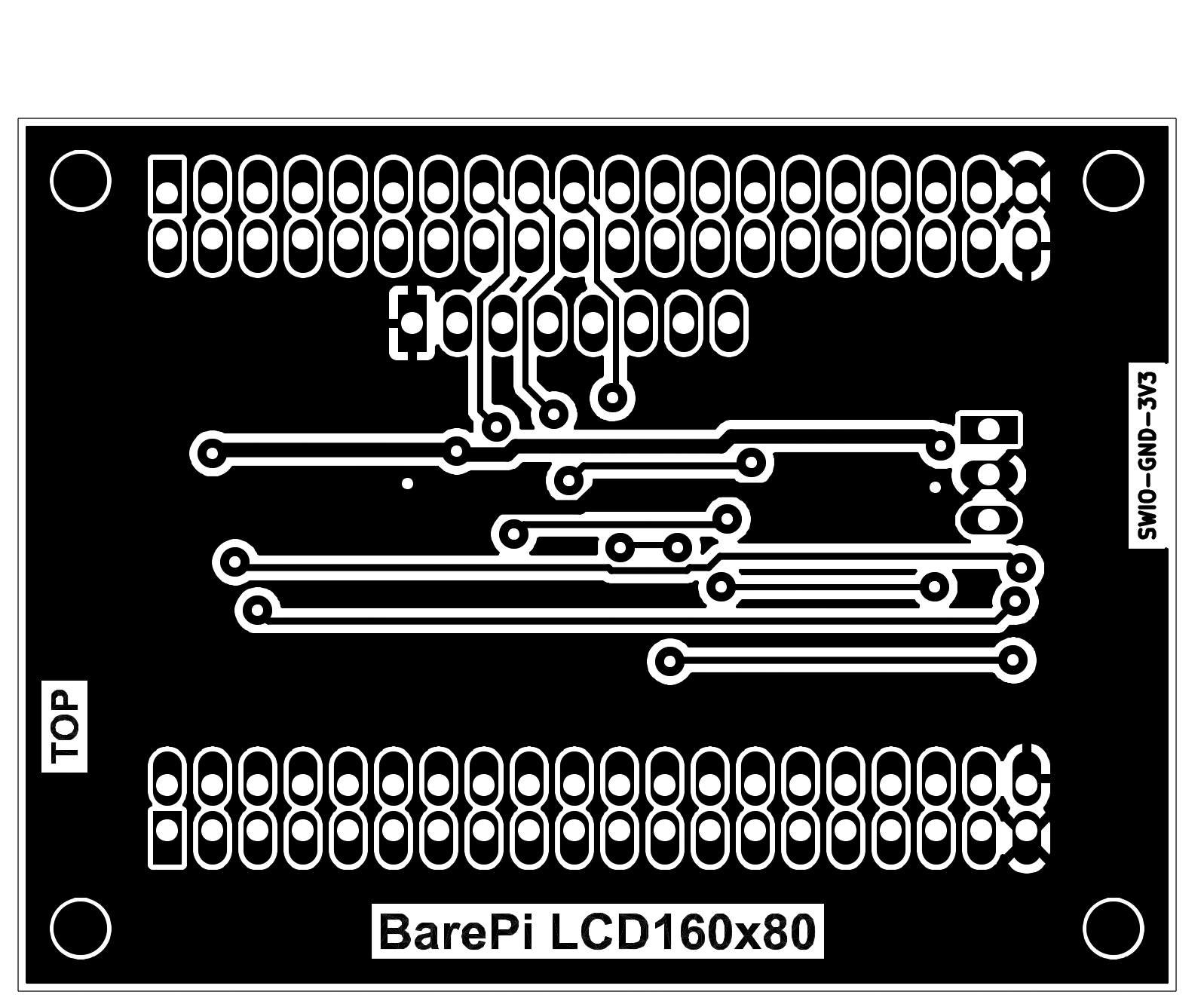
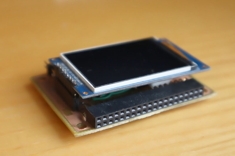
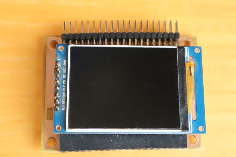
The "LCD160x80" module is a 0.96" graphic color display with SPI interface, 160x80 resolution and ST7735S controller. The module optionally contains a CH32V002J4M6 processor, but it is not necessary to use it, it is only used to identify the module's connection to the bus. The processor is connected to the I2C bus at address 0x30. Although the module has two solder jumpers for selecting the I2C address, the firmware does not use these jumpers. For easier identification of the display connection, an optional resistor R1, connected between the LCD_RES and LCD_CS signals, is also used. Using solder jumpers, you can choose whether to use the display backlight signal from the bus or whether it will be generated by the processor in the module. It may happen that some processor module will not be able to generate adjustable backlight brightness, in which case it may be more appropriate to generate the backlight in the display module.
The PiLibSDK library contains driver for controlling SPI LCD displays in the drv_lcd.* files located in the _drv folder. The driver allows detection of the LCD160x80 module connection. It uses a 15K resistor connected between the RES and CS pins for detection, so it is recommended that the module be equipped with this detection resistor.
The processor firmware can be found in the CH32LibSDK library in the ch32\BAREPI\LCD160x80\ folder (GitHub: https://github.com/Panda381/CH32LibSDK/tree/main/ch32/BAREPI/LCD160x80 ).
In the PiLibSDK library, you’ll find the device driver in drv_lcd.* (GitHub: https://github.com/Panda381/PiLibSDK/tree/main/_drv ).
In the PiLibSDK library, you’ll find the test program in Apps\TEST\LCD (GitHub: https://github.com/Panda381/PiLibSDK/tree/main/Apps/TEST/LCD ).

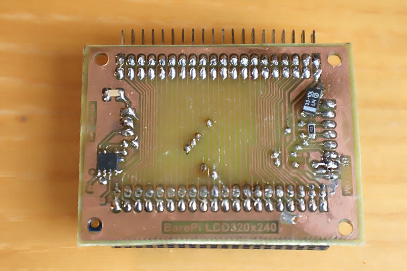
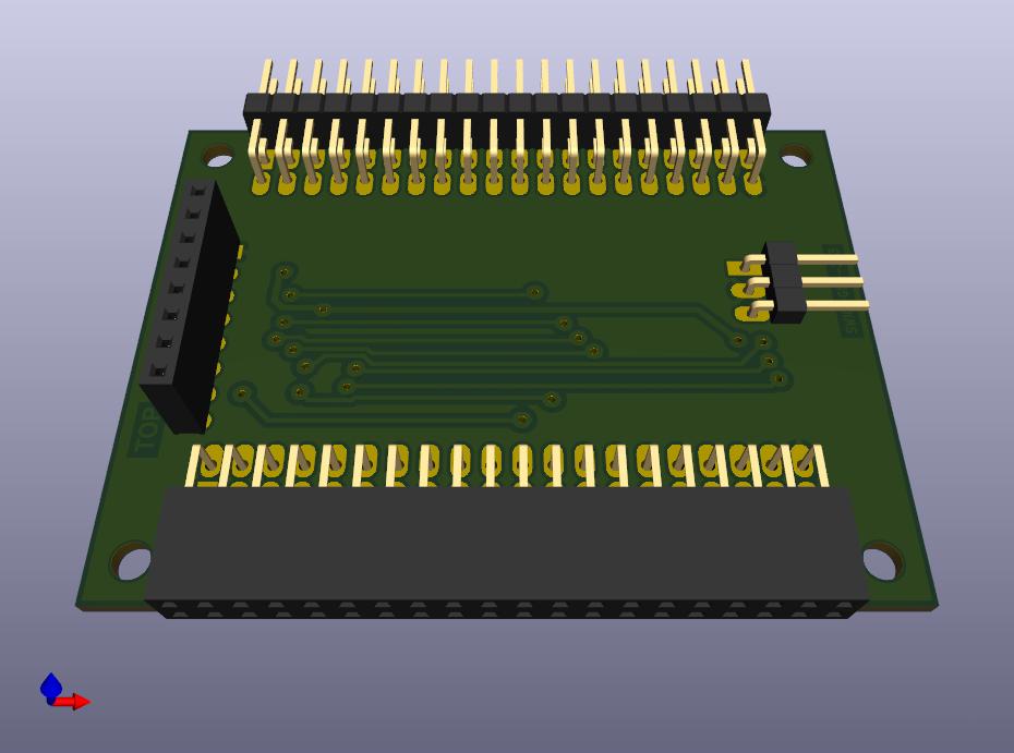
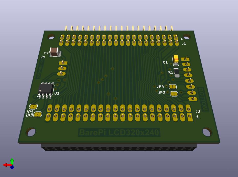
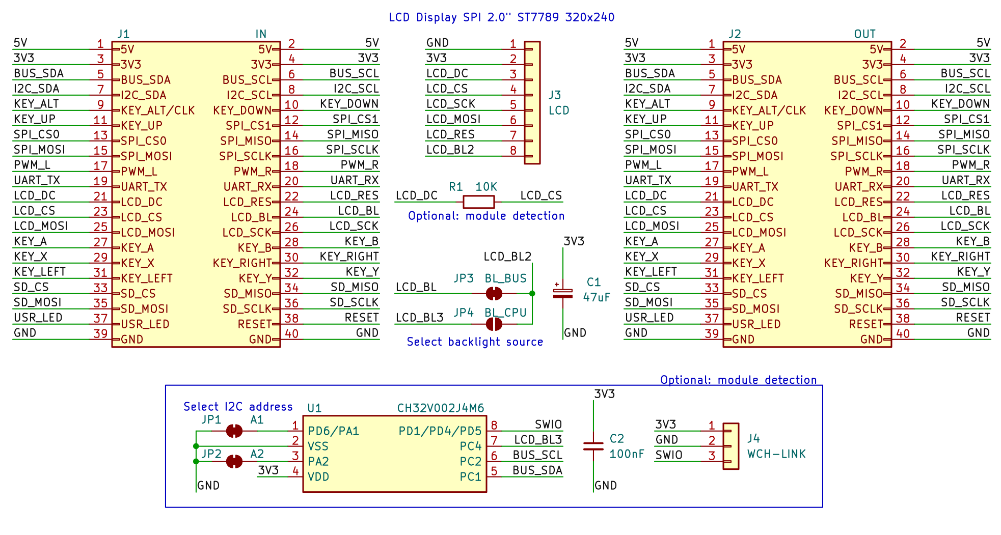
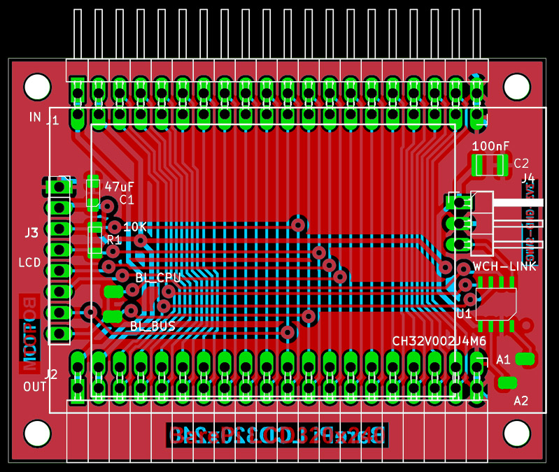
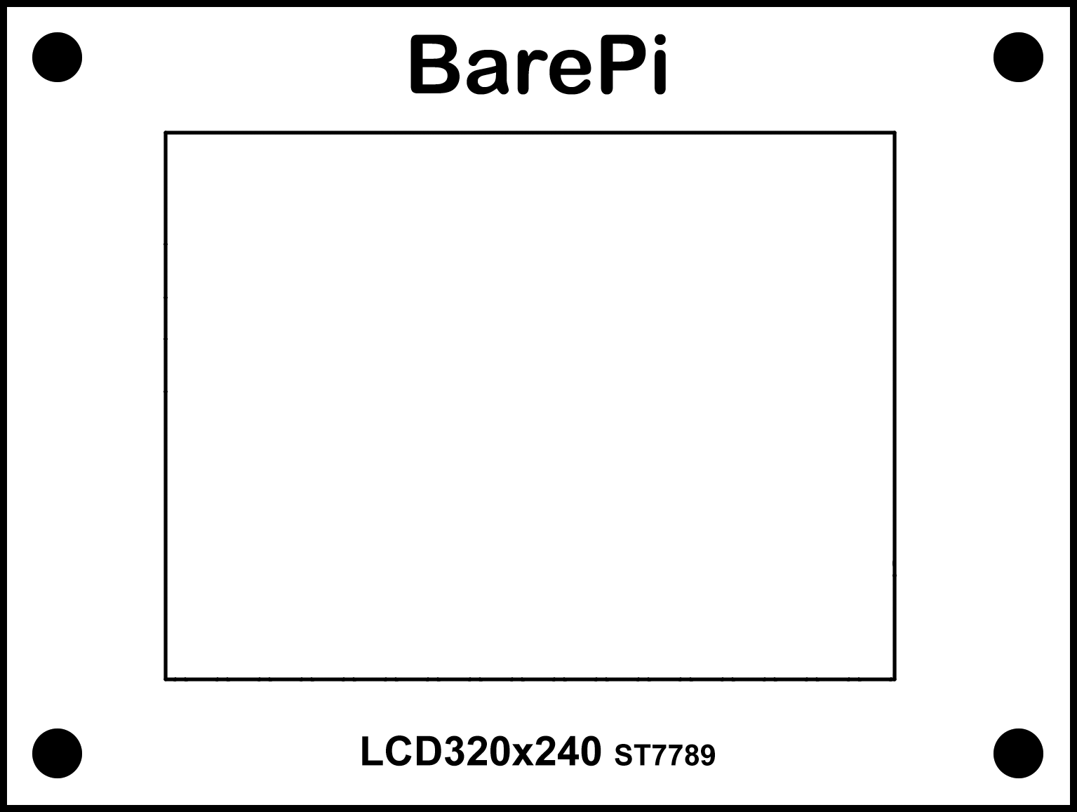
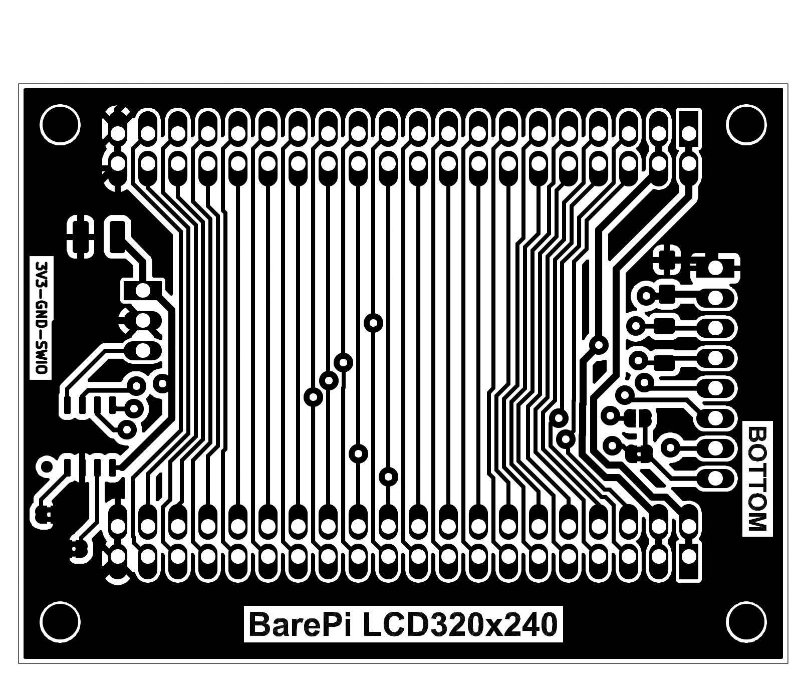
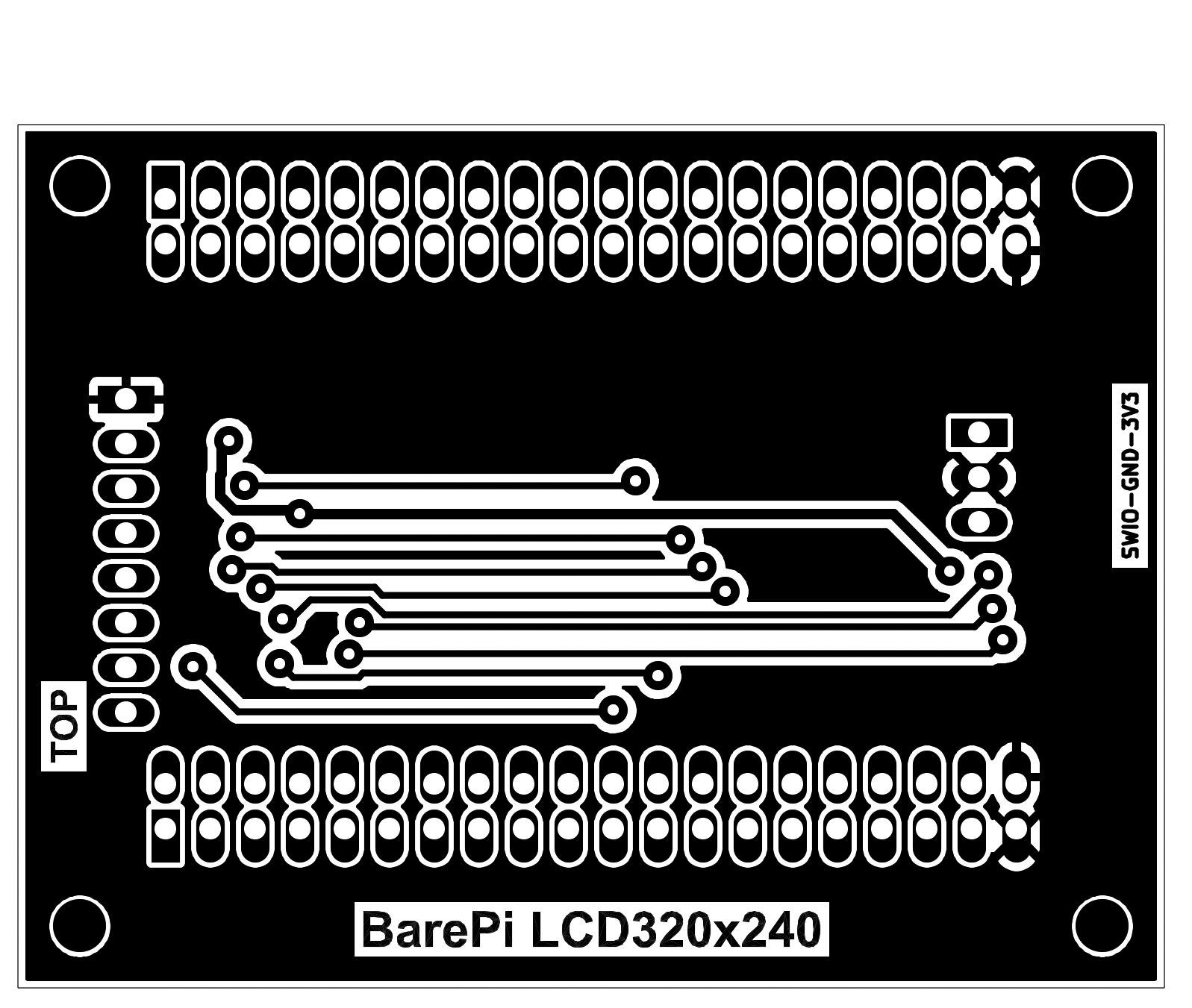
The "LCD320x240" module is a 2.0" graphic color display with SPI interface, 320x240 resolution and ST7789 controller. The module optionally contains a CH32V002J4M6 processor, but it is not necessary to use it, it is only used to identify the module's connection to the bus. The processor is connected to the I2C bus at address 0x30. Although the module has two solder jumpers for selecting the I2C address, the firmware does not use these jumpers. For easier identification of the display connection, an optional resistor R1, connected between the LCD_DC and LCD_CS signals, is also used. Using solder jumpers, you can choose whether to use the signal for the display backlight from the bus or whether it will be generated by the processor in the module. It may happen that some processor module will not be able to generate adjustable backlight brightness, in which case it may be more appropriate to generate the backlight in the display module.
The PiLibSDK library contains drivers for SPI LCD displays in the drv_lcd.* files located in the _drv folder. The driver enables detection of the "LCD320x240" module when it is connected. It uses a 15K resistor connected between the DC and CS pins for detection, so it is recommended that the module be equipped with this detection resistor. Devices with a Raspberry Zero 1 or 2 module can be used with a 320x240 LCD SPI display, with an ST7789 controller, wired according to the "LCD320x240" module. If a program using the PiLibSDK library detects that a display is connected (via the detection resistor), it will automatically send the image to that display. If you want to be able to disable the LCD output on the end device, you can do so using a switch that connects the 15K detection resistor. Detection occurs when the application or loader starts - so after changing the switch, you must terminate or start the program or loader. Disabling the output to the LCD display ensures faster program execution, as sending data to the LCD display places a significant load on the program.
The processor firmware can be found in the CH32LibSDK library in the ch32\BAREPI\LCD320x240\ folder (GitHub: https://github.com/Panda381/CH32LibSDK/tree/main/ch32/BAREPI/LCD320x240 ).
In the PiLibSDK library, you’ll find the device driver in drv_lcd.* (GitHub: https://github.com/Panda381/PiLibSDK/tree/main/_drv ).
In the PiLibSDK library, you’ll find the test program in Apps\TEST\LCD (GitHub: https://github.com/Panda381/PiLibSDK/tree/main/Apps/TEST/LCD ).
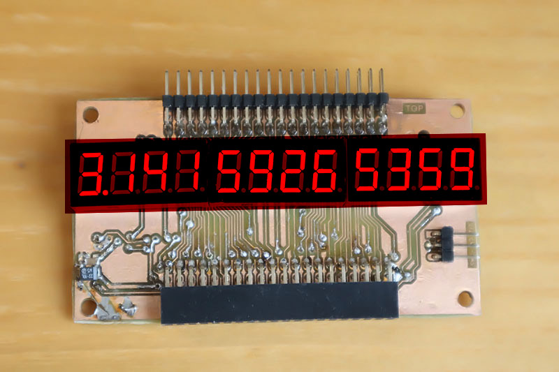
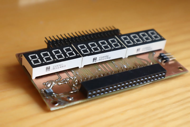
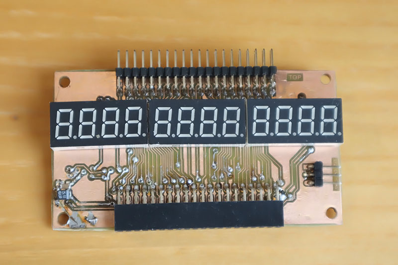
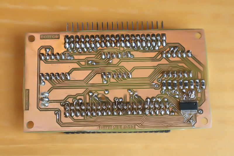
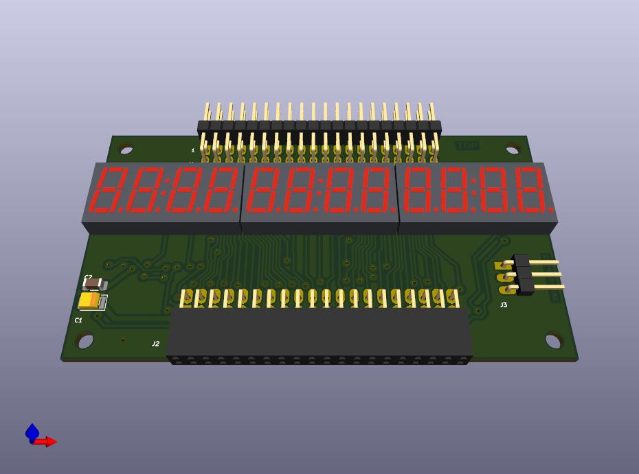
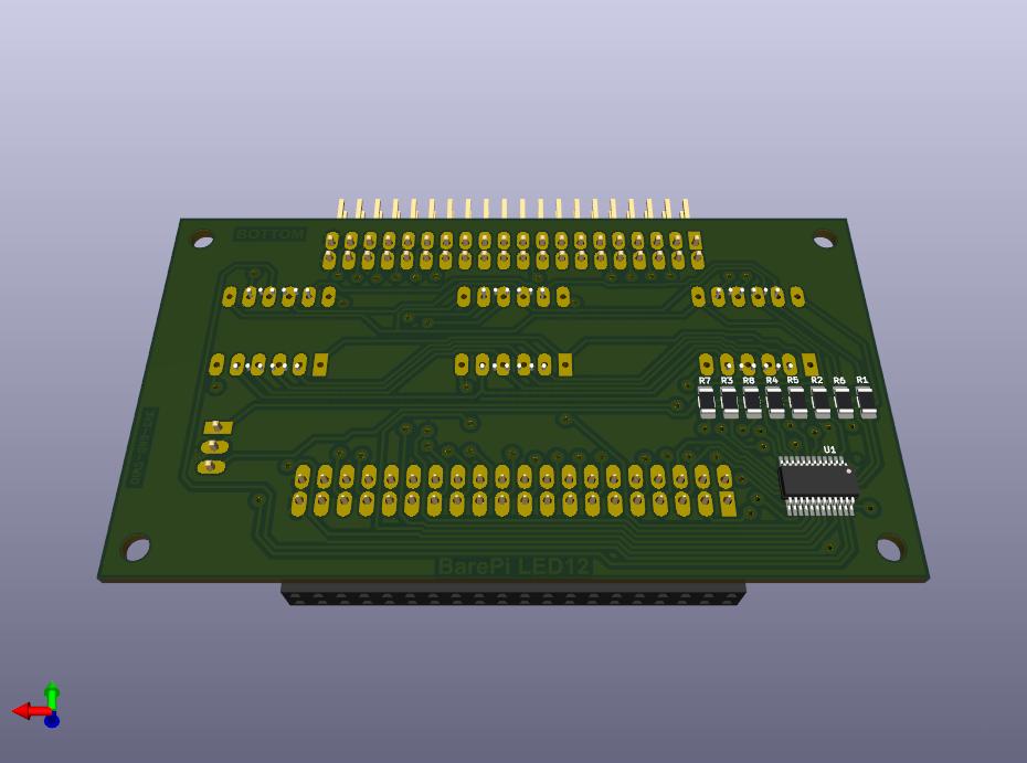
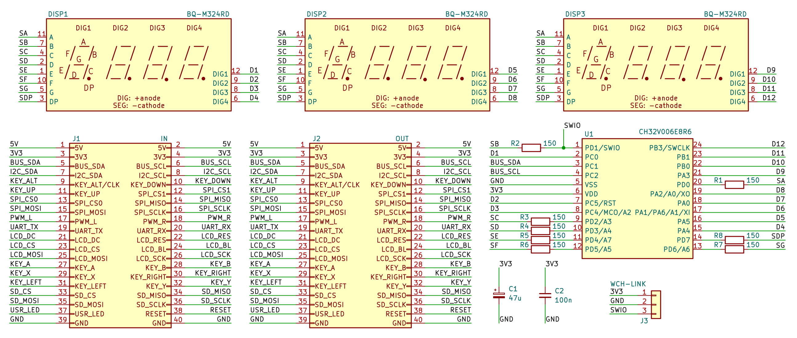
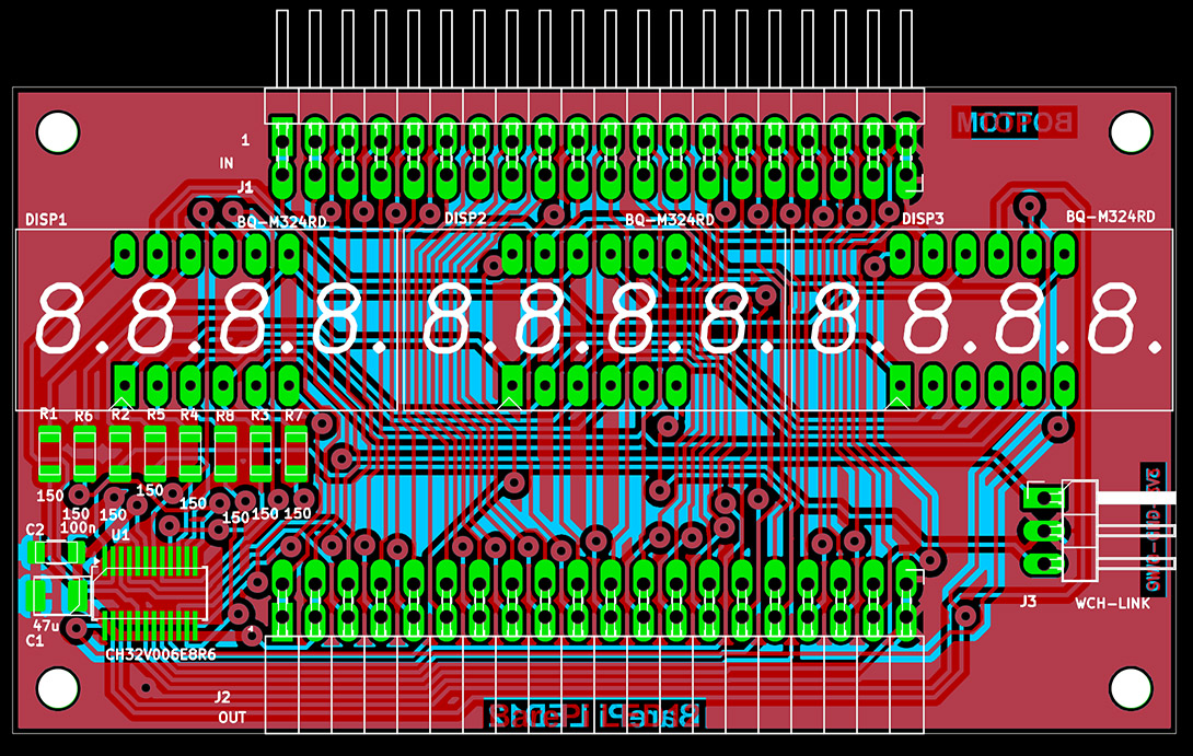
The "LED12" module contains a 12-digit display of 7-segment LED digits. It is controlled by a CH32V006E8R6 processor, which communicates with the main processor via the I2C bus at address 0x32. When building the module, I recommend placing a red plexiglass sheet over the display to increase the contrast of the displayed data. The current to the segments must be limited due to the current limitations of the processor’s pins, so the display’s brightness is low, especially in daylight. It would be better to add drivers to the display’s anodes or to use a circuit with serial-to-parallel converters.
The processor firmware can be found in the CH32LibSDK library in the ch32\BAREPI\LED12\ folder (GitHub: https://github.com/Panda381/CH32LibSDK/tree/main/ch32/BAREPI/LED12 ).
In the PiLibSDK library, you’ll find the device driver in drv_led12.* (GitHub: https://github.com/Panda381/PiLibSDK/tree/main/_drv ).
In the PiLibSDK library, you’ll find the test program in Apps\TEST\LED12 (GitHub: https://github.com/Panda381/PiLibSDK/tree/main/Apps/TEST/LED12 ).
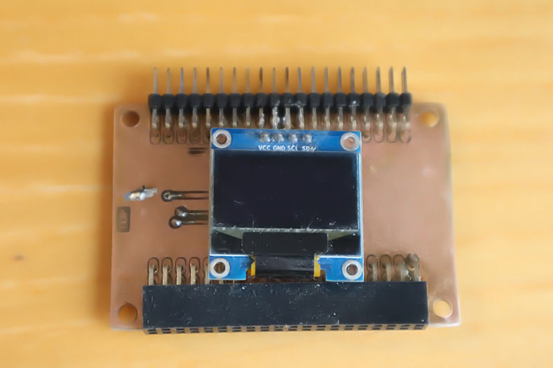
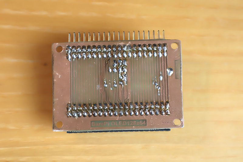
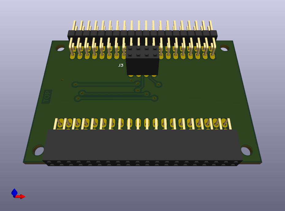
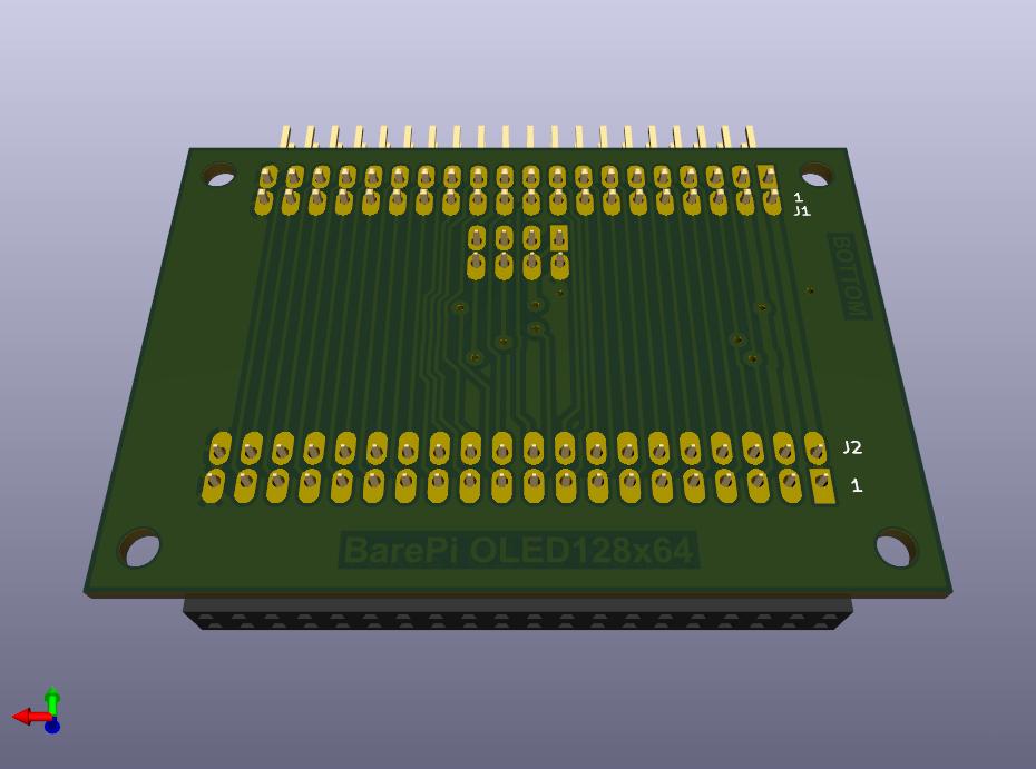
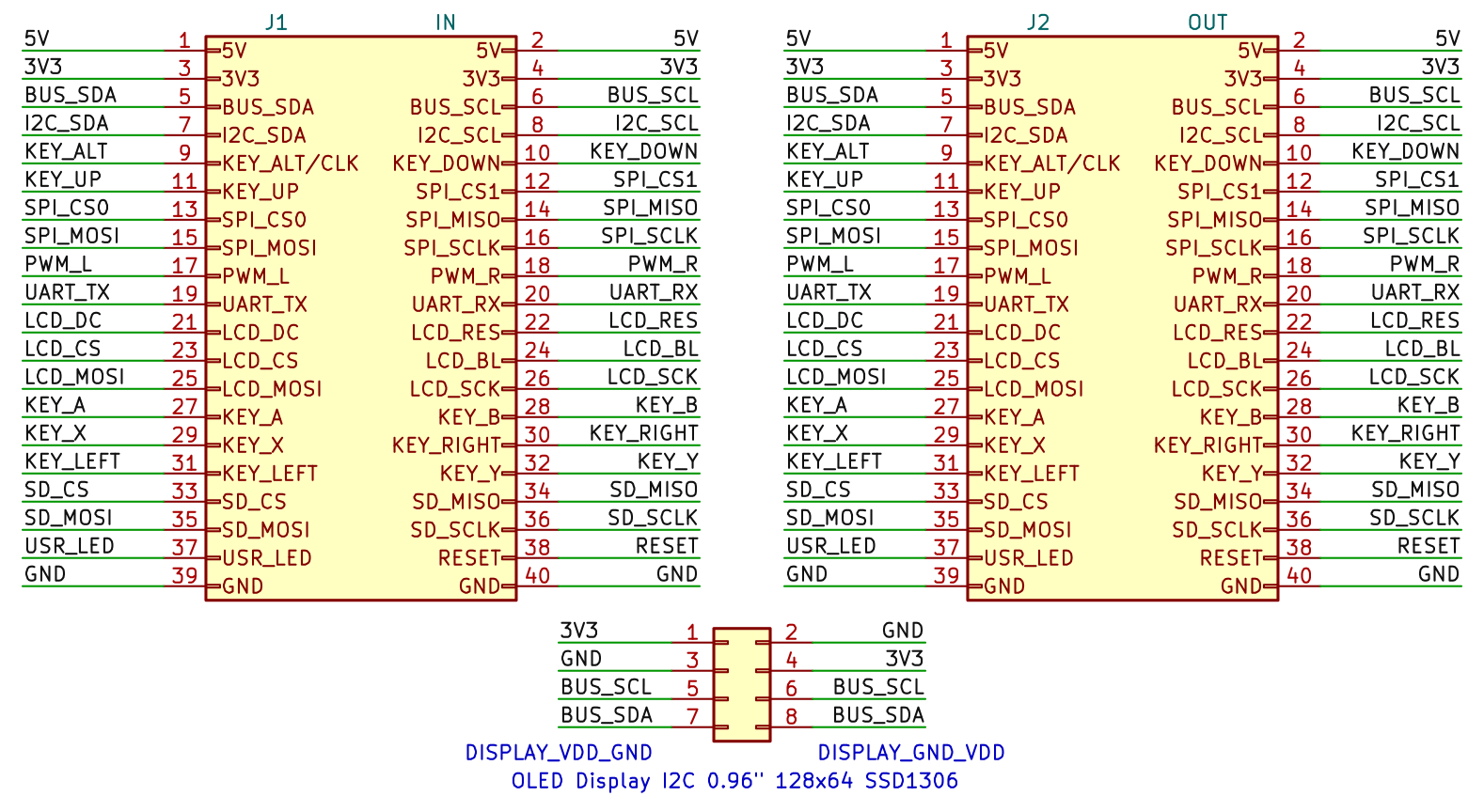
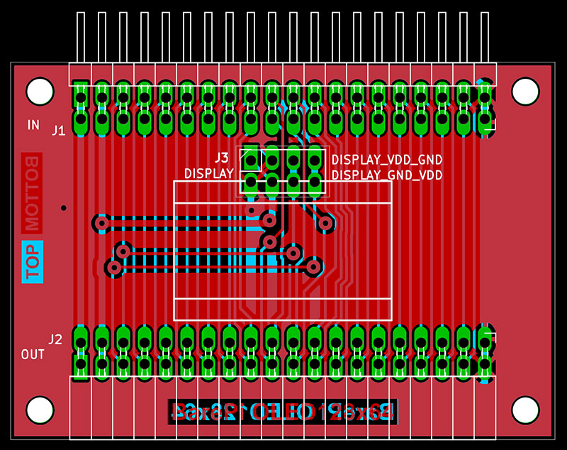
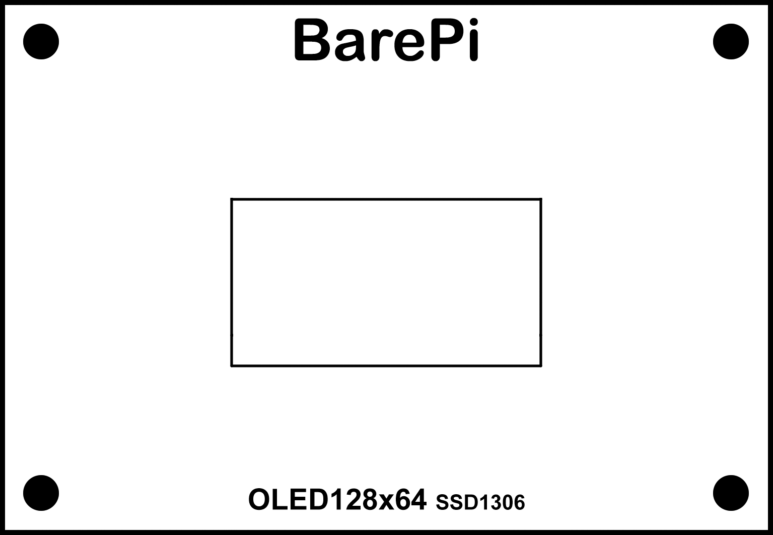
The "OLED128x64" module is a 0.96" black and white OLED display with an I2C interface, a resolution of 128x64 and an SSD1306 controller. The module can be equipped with two types of OLED displays, with different pin arrangements. You can insert the display into the upper or lower position of the header, depending on the desired pin arrangement. For this reason, there are also two different definitions of the module's front panel. In fact, you can use only one panel, printed on both sides, with the back side printed "upside down". You will then use the side of the panel that matches the position of the display used. The PiLibSDK library contains driver for I2C displays with SSD1305 through SSD1309 controllers in the drv_ssd1306.* files located in the _drv folder (GitHub: https://github.com/Panda381/PiLibSDK/tree/main/_drv ).
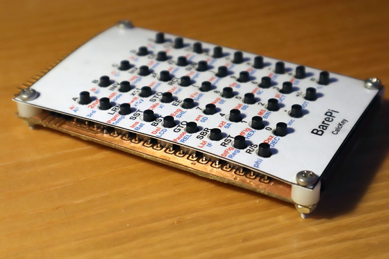
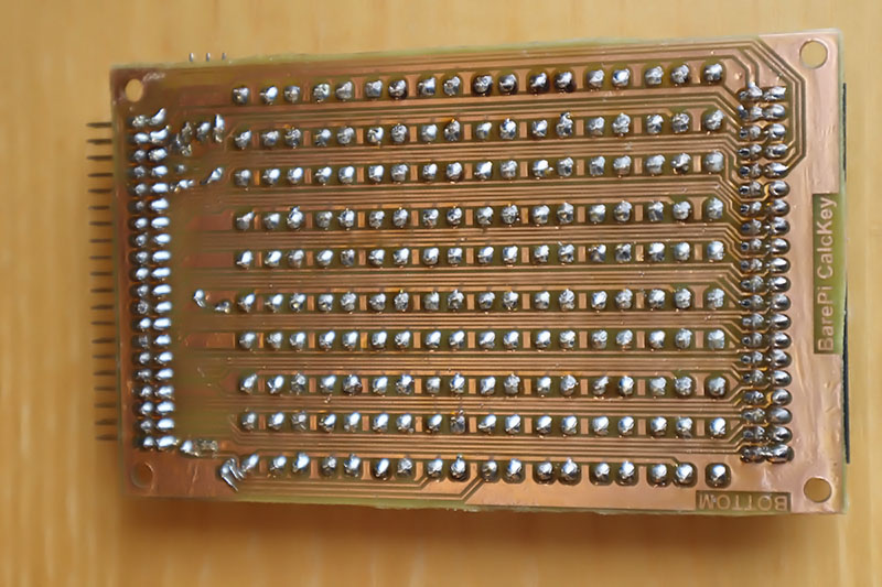
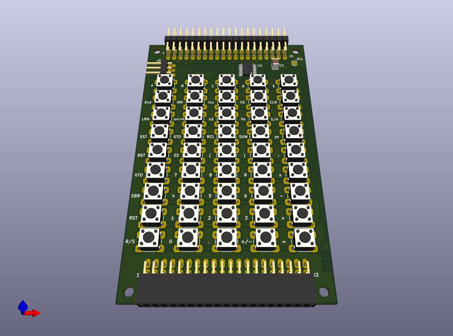
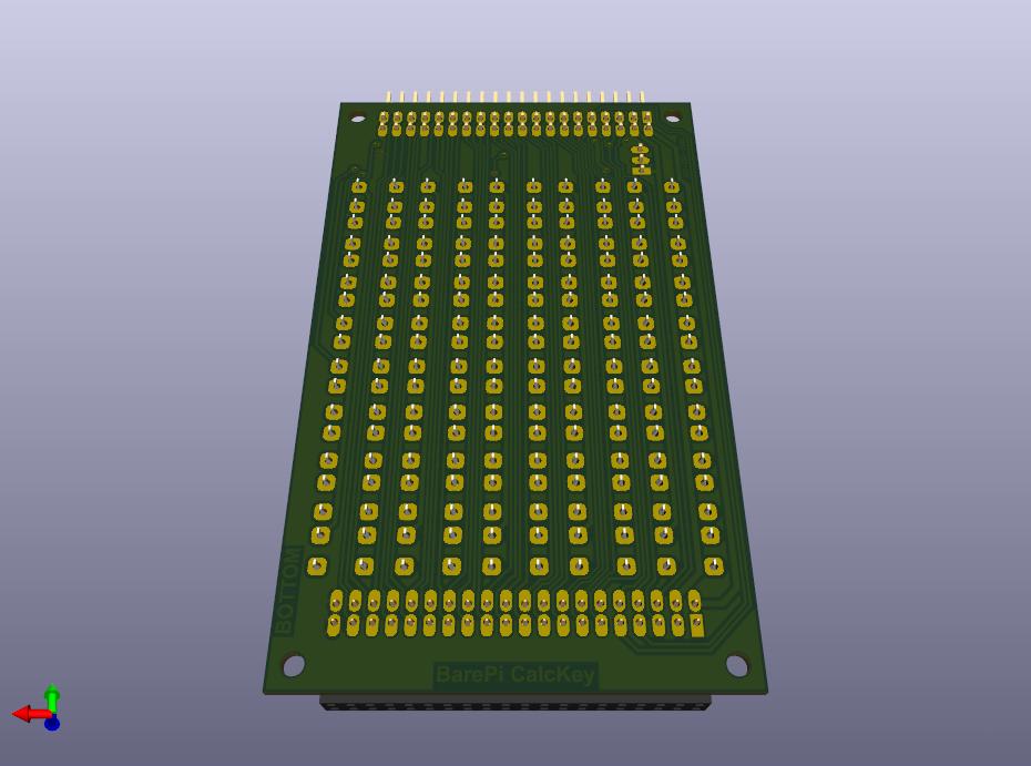
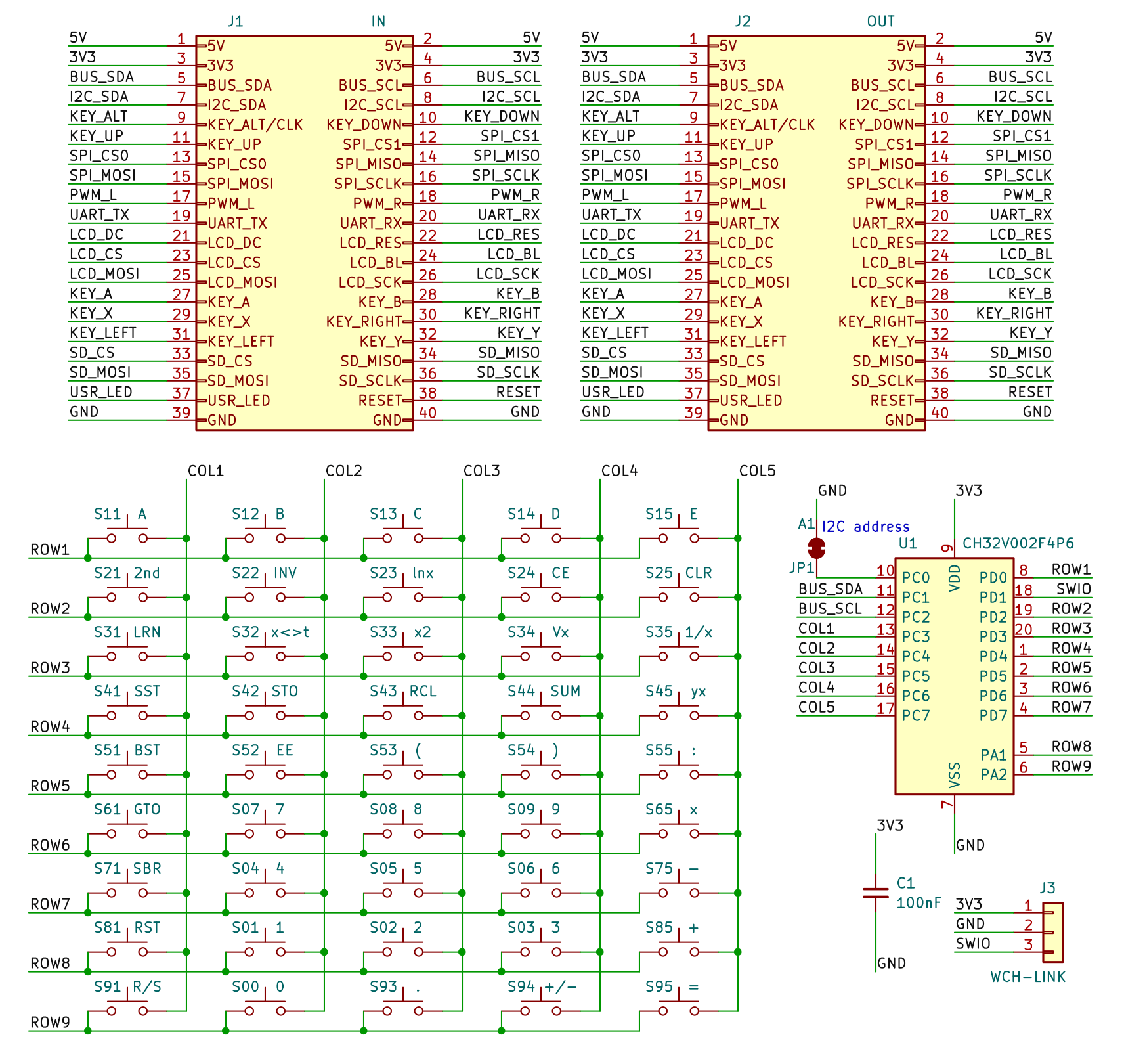
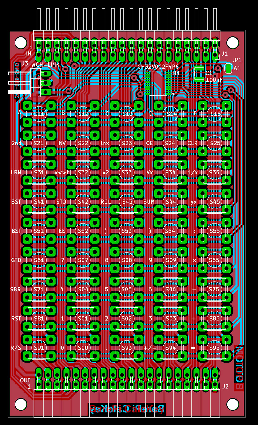
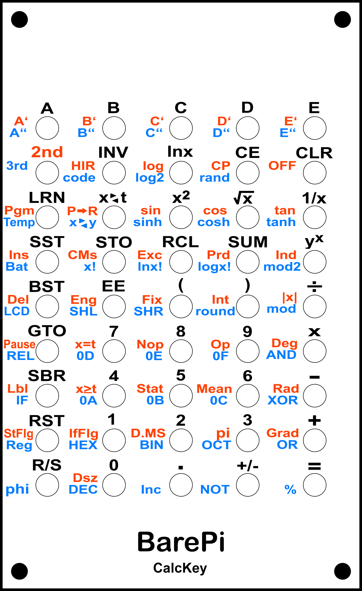
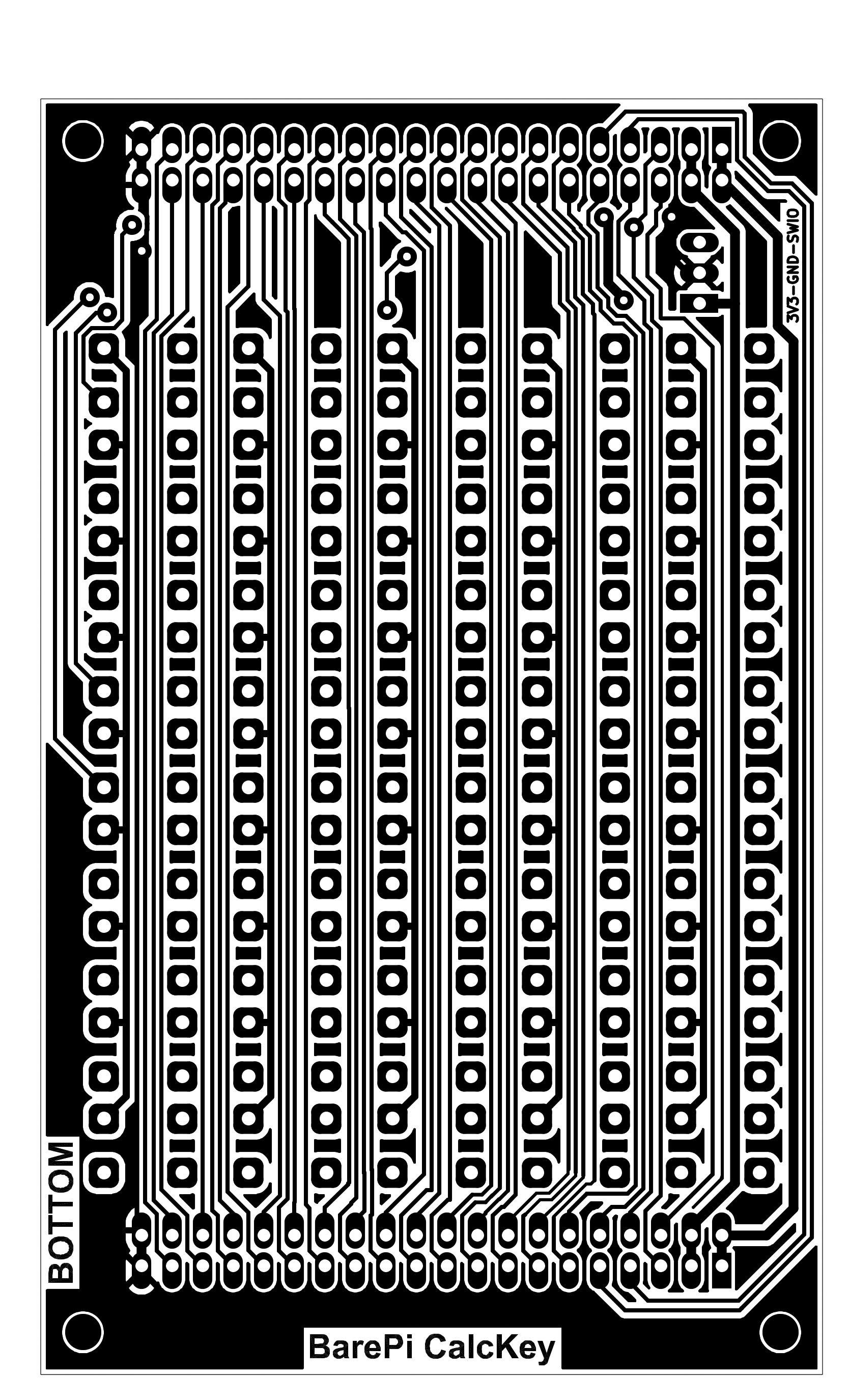
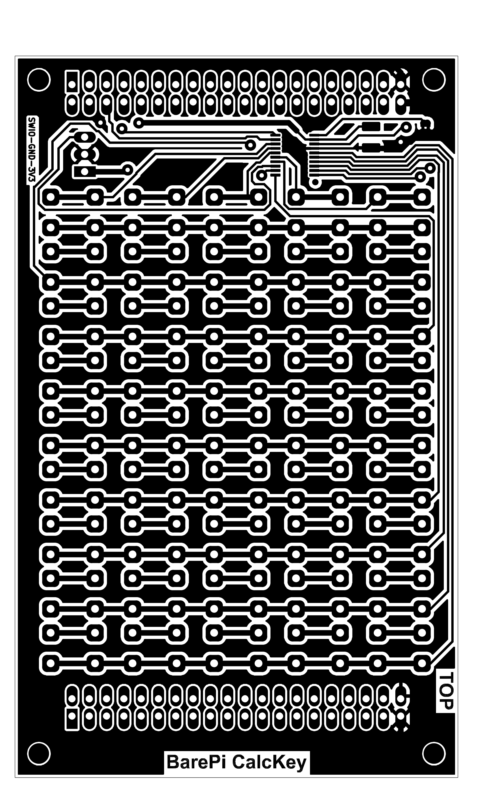
The "CalcKey" module is a keyboard designed for calculators. The layout of the buttons corresponds to the layout of the ET-58 calculator, which is a clone of the TI-58 calculator. If you use a different calculator, you may need different key labels. You can make a mask with different labels, for example, by printing it on hard paper, covering the surface with insulating tape (for better abrasion resistance) and punching the holes for the buttons with a punch on the leather. The keyboard is controlled by the CH32V002F4P6 processor, which communicates with the main processor via the I2C bus at address 0x35. Although the module includes a solder jumper for selecting the I2C address, the firmware does not use this jumper.
The processor firmware can be found in the CH32LibSDK library in the ch32\BAREPI\CALCKEY\ folder (GitHub: https://github.com/Panda381/CH32LibSDK/tree/main/ch32/BAREPI/CALCKEY ).
In the PiLibSDK library, you’ll find the device driver in drv_calckey.* (GitHub: https://github.com/Panda381/PiLibSDK/tree/main/_drv ).
In the PiLibSDK library, you’ll find the test program in Apps\TEST\CALCKEY (GitHub: https://github.com/Panda381/PiLibSDK/tree/main/Apps/TEST/CALCKEY ).
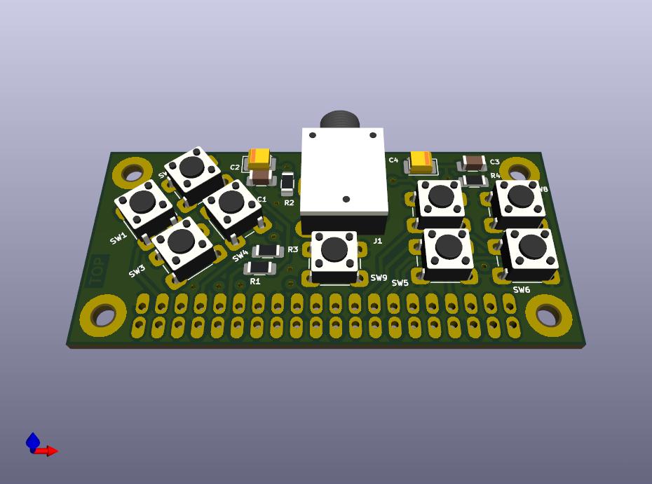
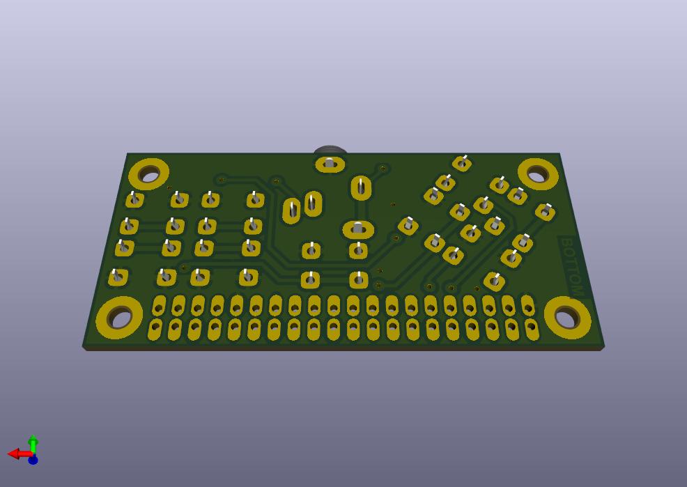
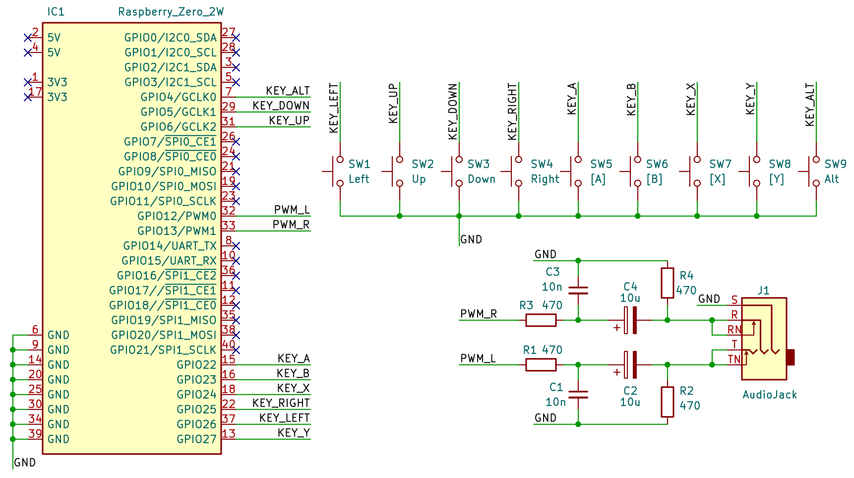
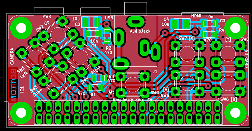
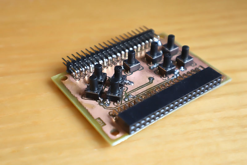
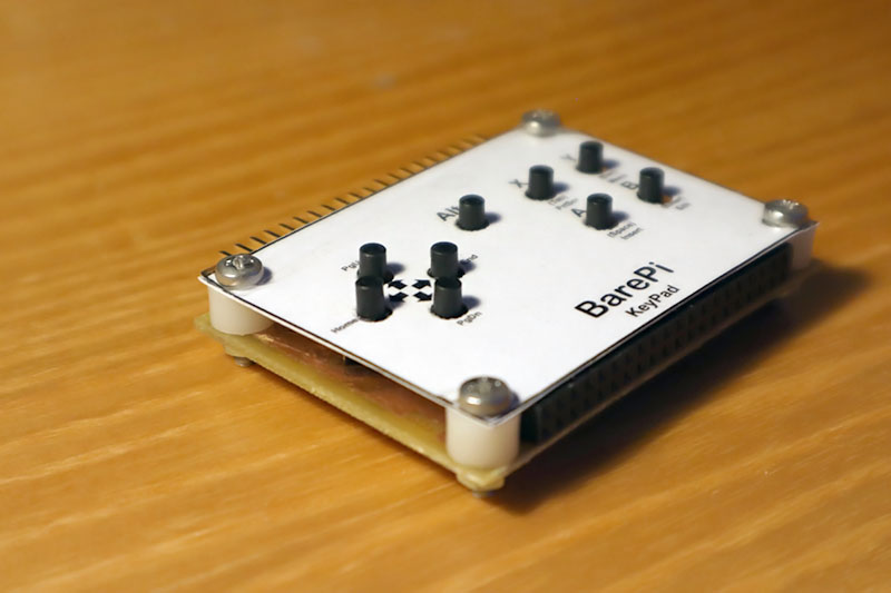
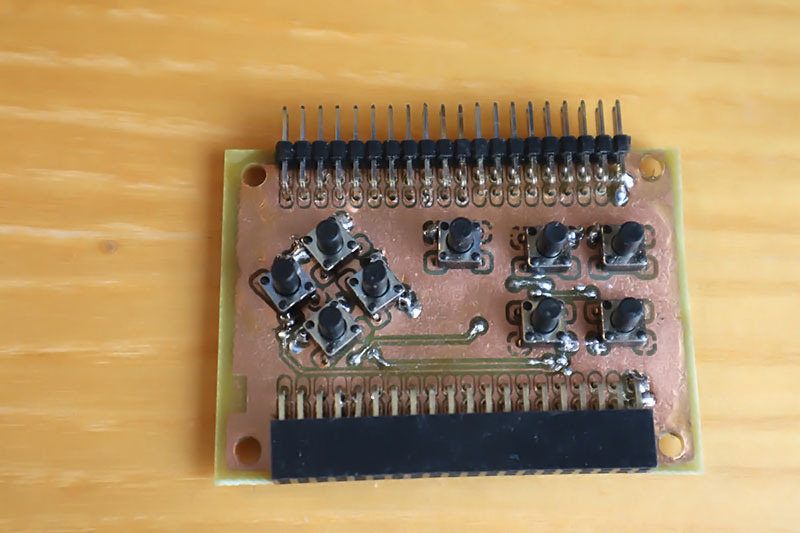
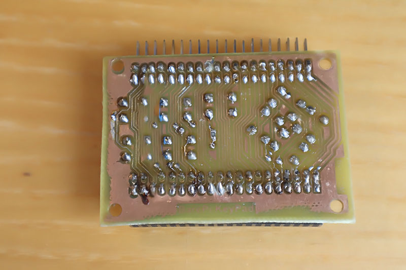
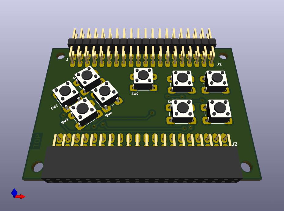
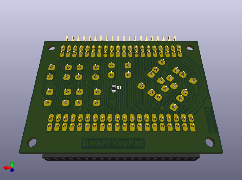
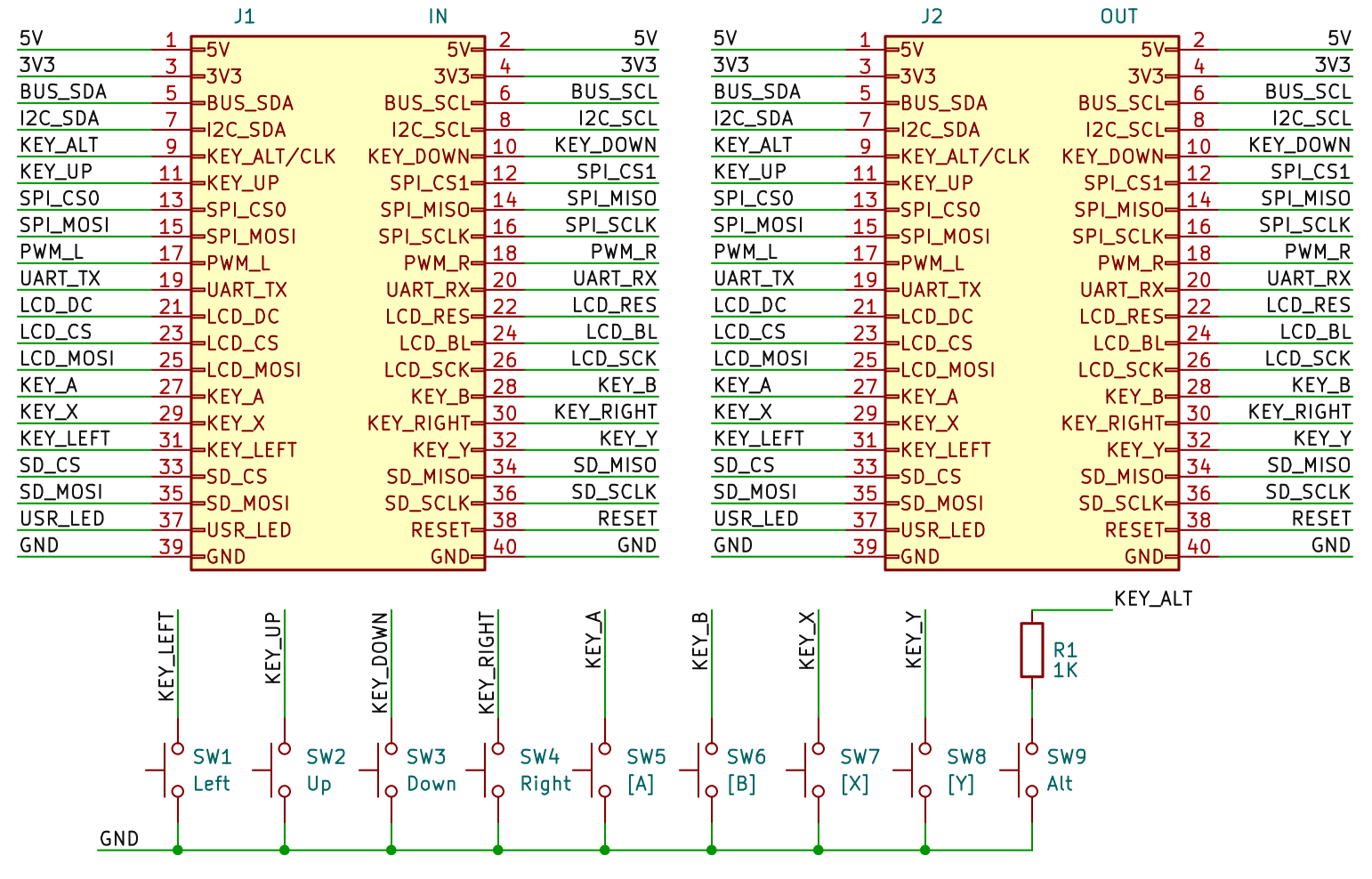
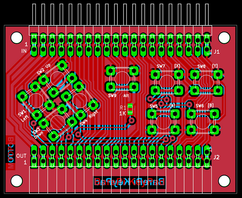
The "KeyPad" module is a basic simple keyboard, used primarily for controlling games. It contains 9 buttons - directional arrows, main action button "A", secondary action button "B", auxiliary button "X", end button "Y" and alternative key meaning button "ALT". The buttons are used for direct reading of the state using pull-up resistors, when pressed they connect to the ground GND. The signal for the "ALT" button can also serve as a clock signal source, therefore the button is connected via a 1K0 protective resistor. The Alt+[A] key combination (= "Zoom") switches the display mode of the built-in LCD screen when the video mode resolution is higher than the LCD screen's resolution.
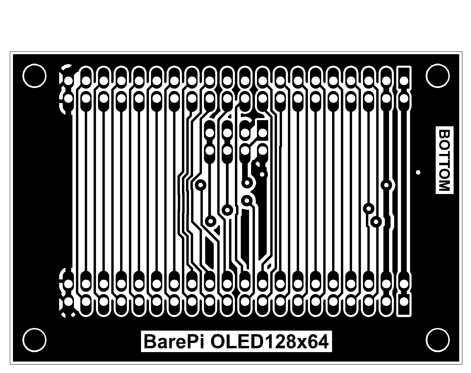
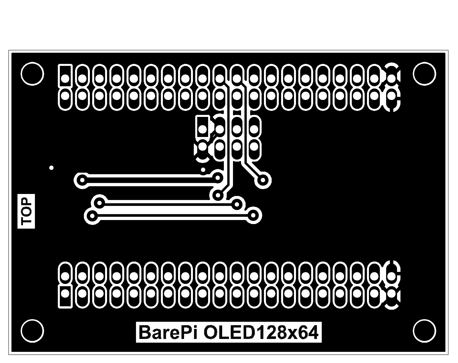
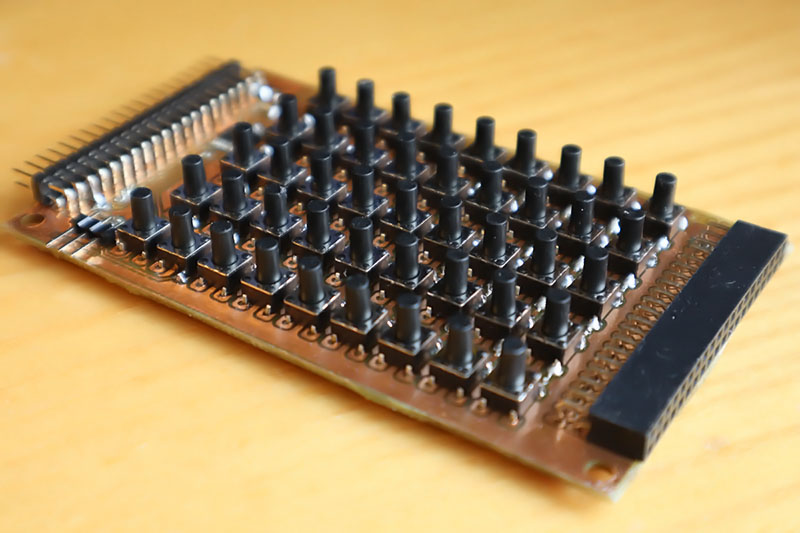
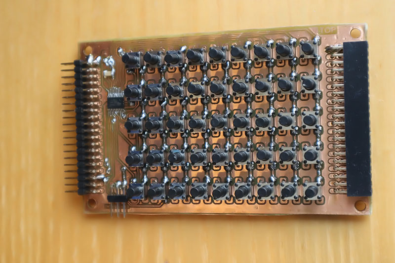
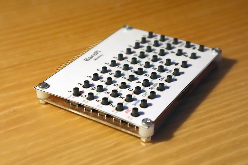
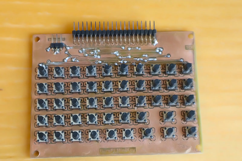
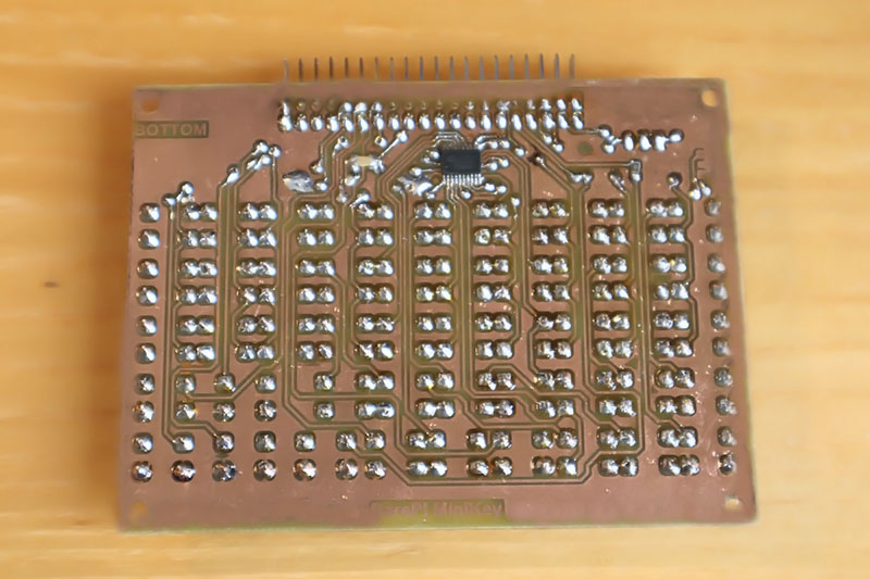
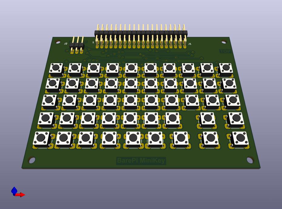
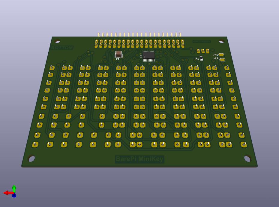
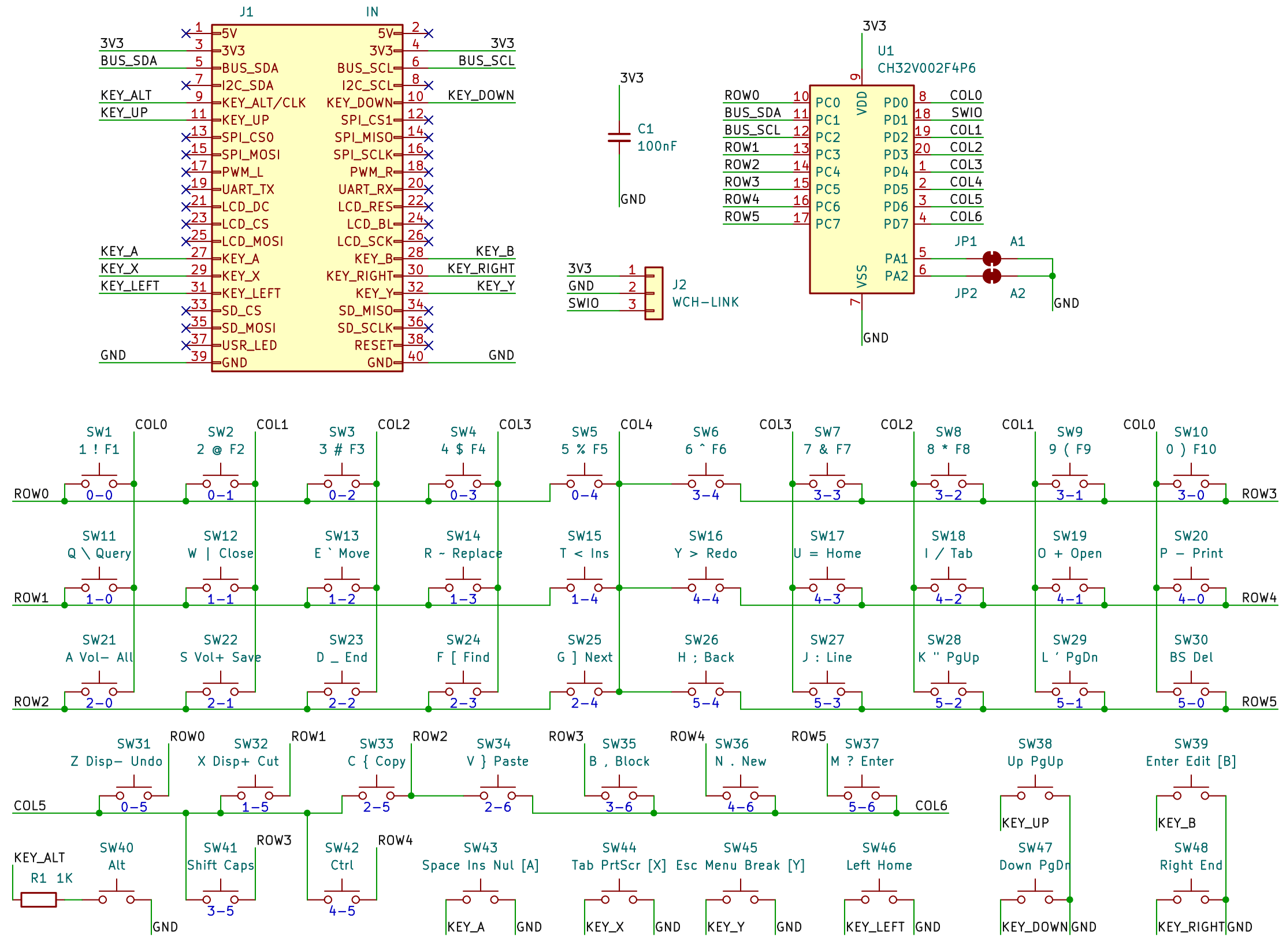
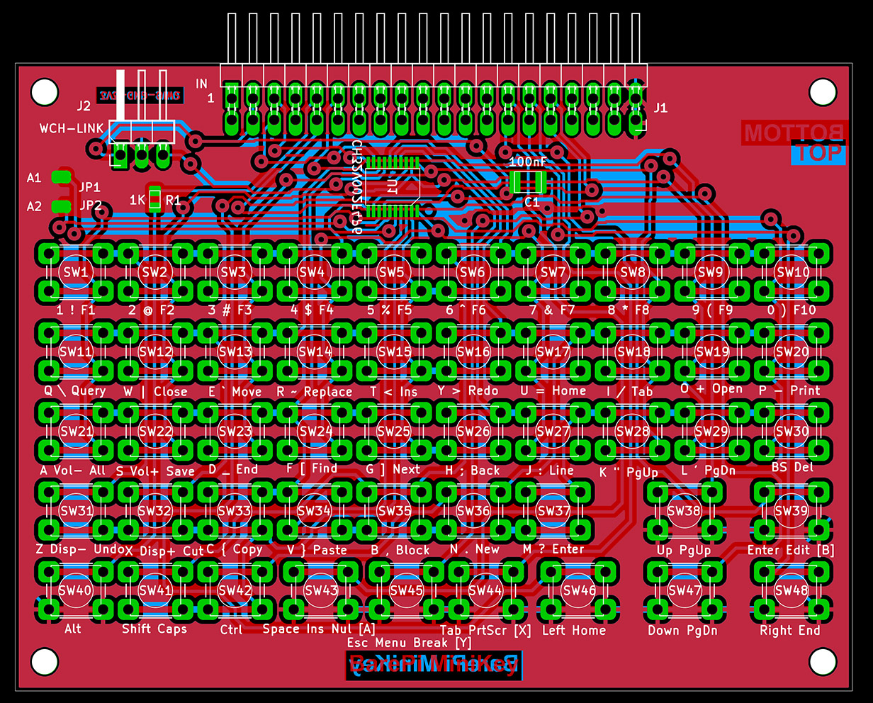
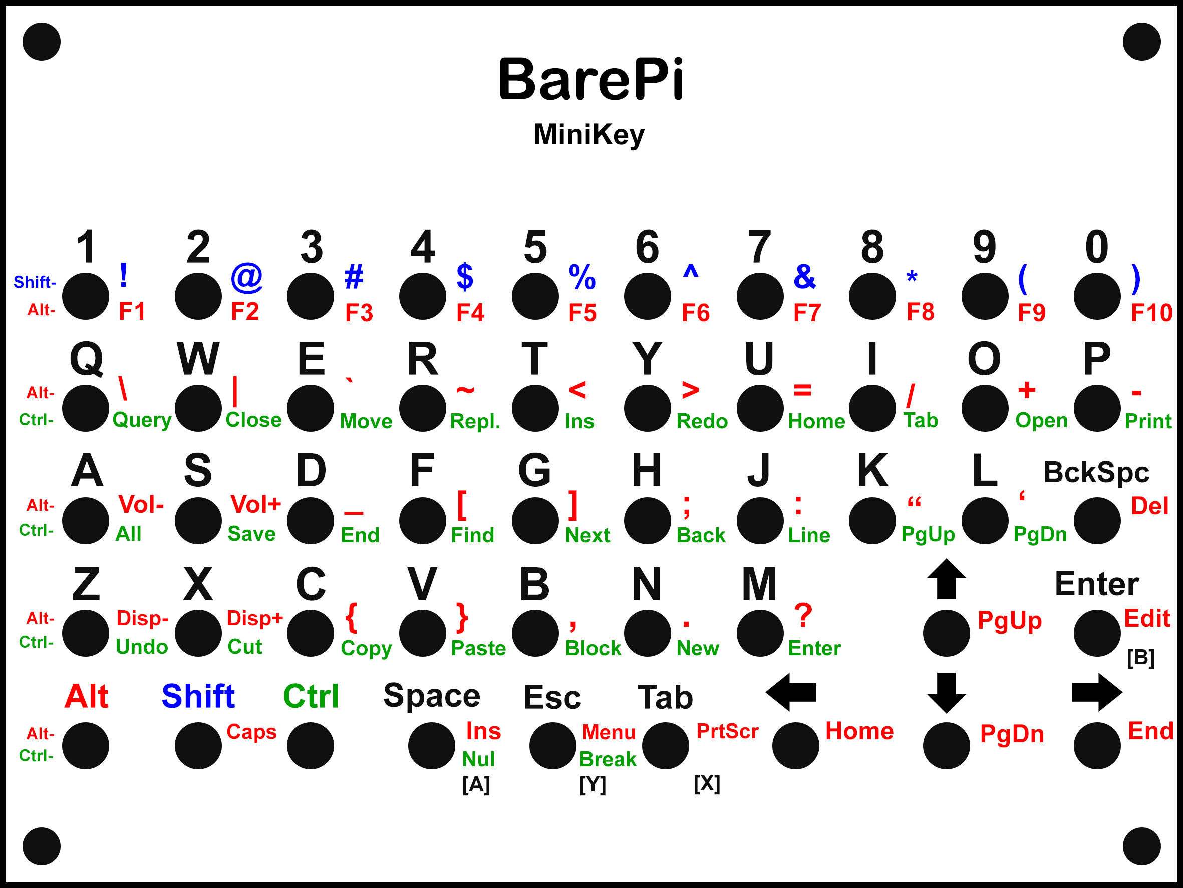
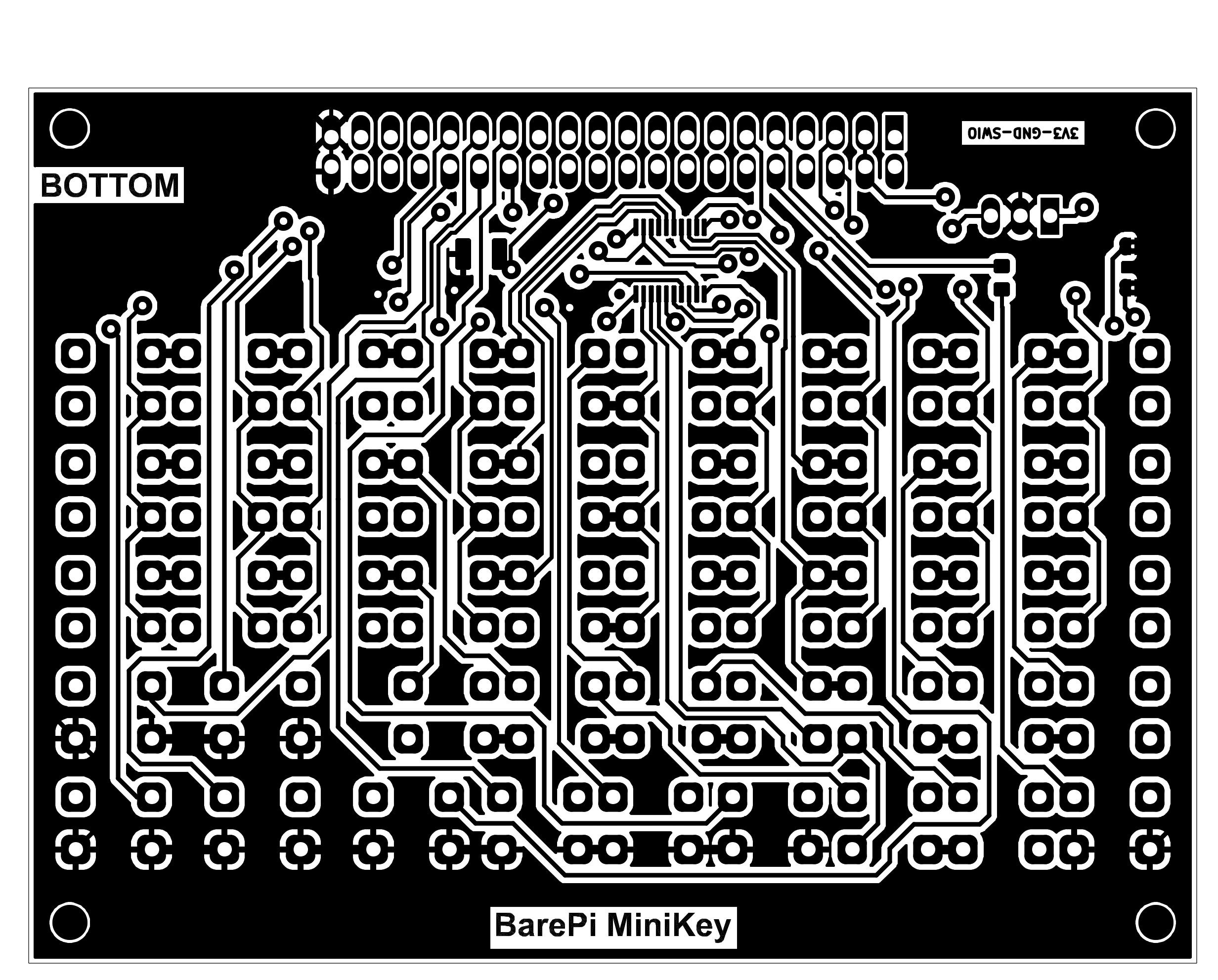
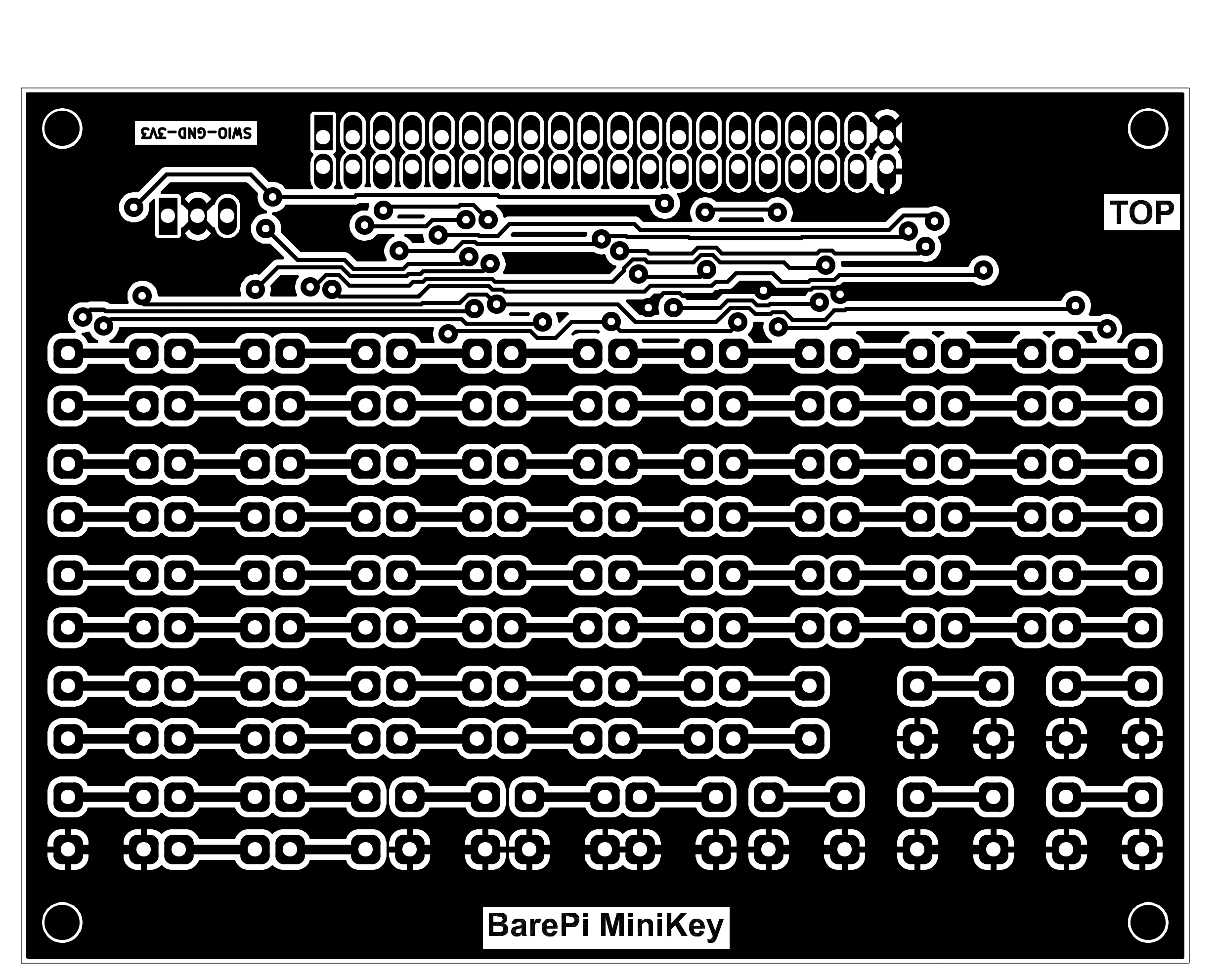
The "MiniKey" module is a minimalistic alphanumeric keyboard. It contains a total of 48 buttons, of which 9 buttons correspond to the "KeyPad" keyboard buttons with direct access to the buttons, the remaining 39 buttons are multiplexed by the CH32V002F4P6 processor, in a 6x7 button matrix. You can make a mask with labels, for example, by printing it on cardstock, covering the surface with adhesive tape (for better abrasion resistance), and punching the holes for the buttons with a leather punch. The processor communicates with the main processor via the I2C bus at address 0x34. Although the module has two solder jumpers for selecting the I2C address, the firmware does not use these jumpers.
The processor’s firmware can be found in the CH32LibSDK library in the ch32\BAREPI\MINIKEY\ folder (GitHub: https://github.com/Panda381/CH32LibSDK/tree/main/ch32/BAREPI/MINIKEY ).
In the PiLibSDK library, you’ll find the device driver in drv_minikey.* (GitHub: https://github.com/Panda381/PiLibSDK/tree/main/_drv ).
In the PiLibSDK library, you’ll find the test program in Apps\TEST\MINIKEY (GitHub: https://github.com/Panda381/PiLibSDK/tree/main/Apps/TEST/MINIKEY ).
Miroslav Nemecek